*Please prepare a license ID and password for the license administrator.
*It is different from the service for JMAG WEB MEMBER (free membership). Please be careful.
Overview

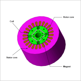
More and more permanent magnet motors are starting to use rare earth magnets, which have a high energy product, in order to achieve higher output density. Neodymium rare earth magnets contain a great deal of iron so they have a high electric conductivity, but when a varying magnetic field is applied they produce Joule loss from eddy currents. Due to the spread of IPM structure adoption and field weakening controls in recent years to speed up rotation, the frequencies and fluctuation ranges of varying fields applied to magnets have increased, and there has been a corresponding increase in Joule loss. By dividing the magnet, like one would a laminated core, to control eddy currents, one can obtain a method of lowering the apparent electric conductivity and lowering the eddy currents. Armature reactions in the stator occur before the eddy currents produced in the magnet, so the eddy currents are determined by the slot geometry of the stator core, the geometry of the rotor, the nonlinear magnetic properties of the core material, and the current waveform that flows through the coil.
In order to examine these kinds of magnet eddy currents ahead of time, one has to account for things like these geometries and material properties precisely, so a magnetic field simulation using the finite element method (FEM), which can account for them, would be the most effective.
In this example, the use of a magnetic field analysis in a state of operation to obtain variations in magnet eddy current losses according to the number of divisions in the magnet.
Eddy Current Density Distribution in the Magnet

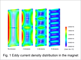
Fig. 1 shows the eddy current density distribution in the magnet. The eddy currents are concentrated on the surface of the magnet. Using a divided magnet breaks up the eddy current paths.
Change of the Loss in Divided Magnet
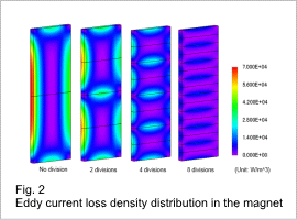
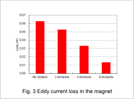
Fig. 2 shows the magnet’s eddy current loss density distribution and Fig. 3 shows the eddy current loss.
By increasing the number of divisions in the magnet, the magnet increases the eddy current flow path and increases the electrical resistance. Because of this, the eddy current density in each divided magnet is reduced as well, making it so that the total amount of eddy current loss decreases.


