Circuit / Control
- Sort condition
- Newest first
- Oldest first
- Large number of views
-

[W-MB-156] Improving Motor Plant Model Accuracy by Accounting for Harmonic Iron Loss
Because of the acceleration of the motor and the effect of the PWM drive, it is becoming more important to account for loss in order to improve accuracy even for analysis using mo…
-
[W-MB-153] Accuracy and Speed Verification of Motor Plant Models Accounting for Spatial Harmonics
This document uses JMAG-RT, which is a type of plant model, to show the relationship between the resolution and accuracy of each axis (mechanical angle, current amplitude, and cur…
-
[W-MB-155] Accuracy of 6-Phase Motor Plant Models for Detecting Faults at Disconnections
Multiphase motors have become widely used, and a fail-safe function can be realized by providing a system with redundancy.
-

[L-MB-28] The Incorporation of JMAG into Model Based Design
The JMAG-provided plant model (JMAG-RT) simulates the characteristics of an actual machine with high-fidelity information, acquired by means of FEA, and realizes a highly reliable…
-

San-Eisha Ltd.
A power distribution equipment manufacturer committed to establishing stable power supply and creating a comfortable living environment. A company that manufactures highly reliabl…
-

Model-Based Solution for Efficient Motor Control System Development
Atsushi Katagiri, MathWorks Japan
-
[JAC229] Analysis of the Effect of PWM on the Iron Loss of an Induction Motor
In this example, we introduce a case study to obtain the iron losses of the induction motor that accounts for the PWM input.
-

Example of Using JMAG-RT for High-Voltage Systems in the Toyota Hybrid System Application to Verification of Feasibility Before Actual Machine Test
Toshifumi Yamakawa, TOYOTA MOTOR CORPORATION
-
[L-MB-30] Accurately Identifying Motor Characteristics During Control with JMAG-RT
In general, the characteristics of motor models used in control circuit simulation of a motor drive system are often assumed to be constant when the motor is in drive mode.
-
[JAC291] Control Simulation of Switching Number of Poles in a 6-Phase Induction Machine
In this document, the behavior of a 6-phase induction motor during the switching of the number of poles is evaluated by simulation.
-
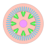
[RTML-051] WFSM_03
Type: WFSM | Max Power: 10(kW) | Stator(Outside Diameter): 115(mm) | Height: 150(mm) | Voltage/Current: DC240(V)/84.8(A), DC300(V)/15(A) | Rotor/Mover: WF | Number of Phases: 3
-
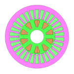
[RTML-056] WFSM_08
Type: WFSM | Max Power: 75(kW) | Stator(Outside Diameter): 400(mm) | Height: 65(mm) | Voltage/Current: DC500(V)/283(A), DC600(V)/50(A) | Rotor/Mover: WF | Number of Phases: 3
-
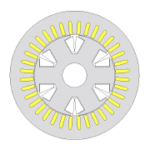
[RTML-055] WFSM_07
Type: WFSM | Max Power: 75(kW) | Stator(Outside Diameter): 212(mm) | Height: 200(mm) | Voltage/Current: DC600(V)/250(A), DC600(V)/45(A) | Rotor/Mover: WF | Number of Phases: 3
-
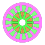
[RTML-053] WFSM_05
Type: WFSM | Max Power: 10(kW) | Stator(Outside Diameter): 185(mm) | Height: 50(mm) | Voltage/Current: DC240(V)/84.8(A), DC300(V)/35(A) | Rotor/Mover: WF | Number of Phases: 3
-
[RTML-054] WFSM_06
Type: WFSM | Max Power: 75(kW) | Stator(Outside Diameter): 212(mm) | Height: 200(mm) | Voltage/Current: DC600(V)/250(A), DC200(V)/20(A) | Rotor/Mover: WF | Number of Phases: 3
-
[RTML-052] WFSM_04
Type: WFSM | Max Power: 10(kW) | Stator(Outside Diameter): 185(mm) | Height: 40(mm) | Voltage/Current: DC240(V)/84.8(A), DC300(V)/50(A) | Rotor/Mover: WF | Number of Phases: 3