Overview
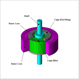
To accurately evaluate the behavior of switching the number of poles during a simulation, the motor model to be controlled must also be highly accurate. The JMAG-RT model is a high-accuracy behavior model created by FEA-based calculations that can express motor characteristics that account for magnetic saturation and slip dependency.
In this document, the behavior of a 6-phase induction motor during the switching of the number of poles is evaluated by simulation.
Control Circuit
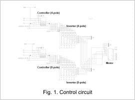
The control circuit is shown in Fig. 1.
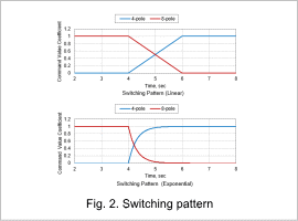
A controller and inverter are arranged for both the 4-pole and 8-pole drive. Use only the 8-pole drive for the time between 0 to 4 sec. For each current command value between 4 and 6 sec, decrease the values for the 8-pole drive and increase the values for the 4-pole drive. After 6 sec and beyond, use only the 4-pole drive.
The switching pattern is shown in Fig. 2. The linear and exponential switching patterns are evaluated here.
Coil Current Waveform (Steady State)
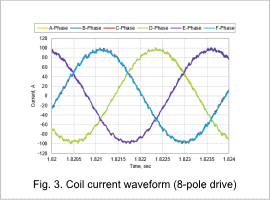
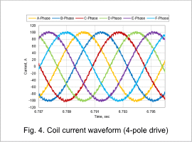
The coil waveforms in the steady state for both the 8-pole drive and 4-pole drive are shown in Fig. 3 and Fig. 4.
In an 8-pole drive, the phase difference is off by 120 deg, similar to a 3-phase sine wave, and in a 4-pole drive, the phase difference is off by 60 deg, similar to a 6-phase sine wave.
Current Waveform on the Controller Side
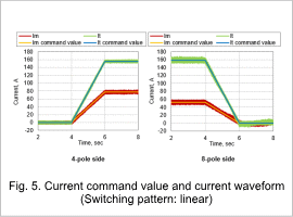
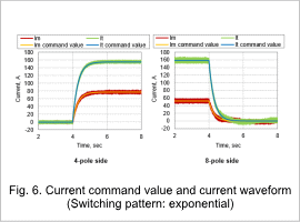
The current command value and current waveform for a linear switching pattern is shown in Fig. 5 and the current command value and current waveform for an exponential switching pattern is shown in Fig. 6.
It can be seen that, the current waveform follows the current command value in each switching pattern.
Torque Waveform
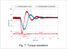
There is a large fluctuation when the number of poles are switched and you can see that the fluctuation is smaller when the switching pattern is linear. However, for practical use, it is necessary to design a system that can further reduce this fluctuation.


