Contents
1. Introduction
2. Disconnection fault detection and the fail-safe function
3. Motor and control specifications
4. Disconnection and verification conditions
5. Plant models
6. Verification results
7. Summary
1. Introduction
Multiphase motors have become widely used, and a fail-safe function can be realized by providing a system with redundancy. While there are examples of 6-phase motors where a 3-phase is duplicated, mutual interference occurs between the 3-phases because the two magnetic circuits of the 3-phase windings are coupled with each other. It is therefore necessary to account for the effect of mutual interference whether the fail-safe function works during disconnections or not.
It is possible to reproduce the behavior of a 6-phase motor by adding a bias 3-phase AC current to a 3-phase spatial harmonic model without modeling a direct 6-phase winding. However, there is the risk of the misdetection of disconnections at operating points where there is strong mutual interference. A 6-phase spatial harmonic model is required for verifying fault detection during disconnections.
2. Disconnection fault detection and the fail-safe function
By having redundancy, a 6-phase motor with two power supplies realizes a fail-safe that can continue to operate even if faults occur in the first system. The mechanism to stop the motor is activated, however, when faults are detected in both of the two systems. As an ECU function verification of a faulty system, it is necessary to verify whether or not a fail-safe is activated when faults are detected in one of the systems.
There are two methods for modeling a 6-phase motor consisting of a duplicated 3-phase when considering plant models. One method is a model accounting for the self and mutual inductance of 6-phase coils (a 6-phase spatial harmonic model). Although this has the advantage of accounting for the mutual interference between the two 3-phases, there is a large amount of calculations involved for generating plant models because of the 6-phase inductance matrix.
The other method is to prepare two 3-phase motors to express 6-phase (a 3-phase bias spatial harmonic model). As a plant model, this advantage has a smaller amount of calculations involved in generating plant models compared to the 6-phase because only 3-phase coils are modeled. The mutual interference between the two 3-phases is not accounted for, however. Magnetic saturation inside the motor is accounted for by adding another 3-phase coil to the 3-phase motor and applying an AC current to match the load. This load-like AC current is handled as a bias component when generating a 3-phase motor plant model, therefore not causing any increases to the amount of calculations involved.
This document shows the plant model accuracy that is required to verify the disconnection detection and fail-safe function of a 6-phase motor using these two plant models.
3. Motor and control specifications
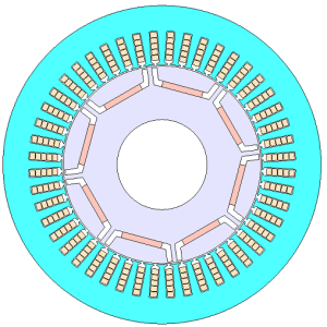
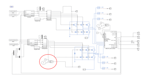
Fig. 1 and Table 1 show the motor specifications. Fig. 2 shows the control model. The control model has two power supply systems, and the current vectors of the two systems are controlled separately by PI control.

Fig. 1 Motor cross-section view
Table 1 Motor specifications
| Number of poles/slots | 8/48 |
| Core material | 35JN270 |
| DC voltage | 600 V |
| Maximum current value | 250 A |
| Carrier frequency | 10 kHz |

Fig. 2 Control model
4. Disconnection and verification conditions
Verification was run with a rotation speed of 3,000 rpm at two operating points with a current amplitude of 10 A and 120 A (a current phase of 36 deg for both). The disconnection condition was that the inverter U-phase lower arm (the red circle in Fig. 2) of system 2 was disconnected at 0.028 sec when the motor drive started.
Protected content here, for members only.
You need to sign in as a Regular JMAG Software User (paid user) or JMAG WEB MEMBER (free membership).
By registering as a JMAG WEB MEMBER, you can browse technical materials and other member-only contents for free.
If you are not registered, click the “Create an Account” button.


