Overview
Usual simulation use sinusoidal inputs for their studies of induction motors but in reality electrical machines are generally fed using Inverter drives that generates PWM signals. For this reason looking at PWM input in FEA simulation would allow to give us a better idea of the losses in an induction motor.
In this example, we introduce a case study to obtain the iron losses of the induction motor that accounts for the PWM input.
PWM
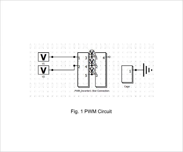
The PWM of the induction motor will be generated using a modified macro of the standard PWM Inverter of JMAG. The PWM Inverter uses the angular positon of the rotor to create the PWM but this cannot be used in a Induction machine setting as the machine does not turn at synchronous speed. We need therefore to Set the PWM to be synchronized with a frequency, in our case 120 Hz and give us a voltage of 40.8 V. The switching frequency was set at 10 kHz.
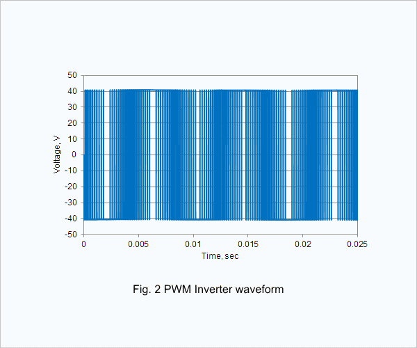
Fig.1 illustrates the circuit used to create the PWM and fig 2 shows the waveform.
Losses in Induction Motor
The study was set so that induction machine rotating at a speed of 3,300 r/min (a slip of 0.0833). To obtain the currents and magnetic flux density in the induction machine we will use a magnetic transient study. The time step was set so that each period of PWM has at least 30 points.
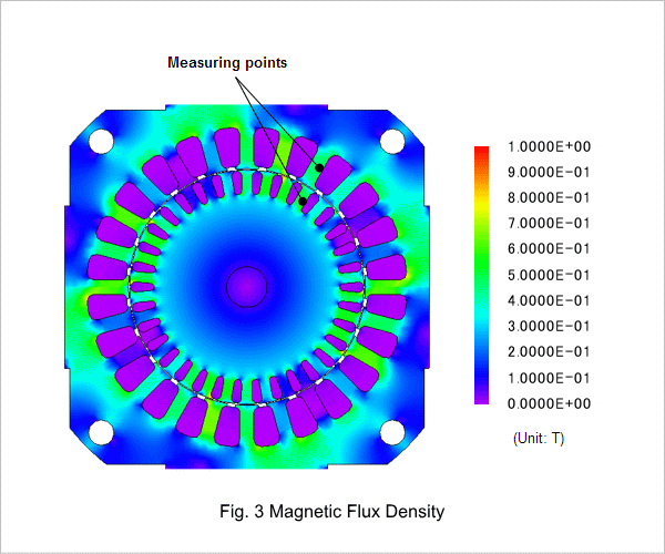
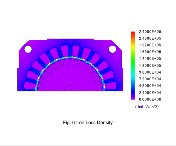
Fig. 3 shows the magnetic flux density of the induction machine. This highlights the areas where the magnetic filed is the most concentrated. The higher magnetic field flux density will also induce more Iron losses.
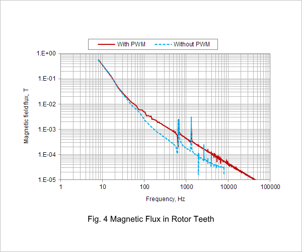
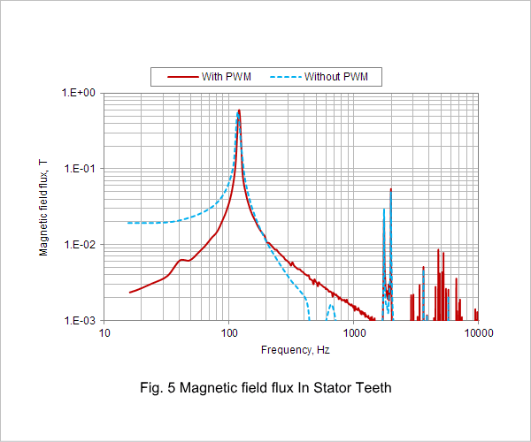
Fig. 4 and fig. 5 shows the FFT of magnetic flux density at the rotor teeth and stator teeth with PWM and without. These show that the losses considering PWM will probably increase due to the harmonics present in the Iron.
Fig. 6 shows the iron loss density distribution.
Iron Loss Study
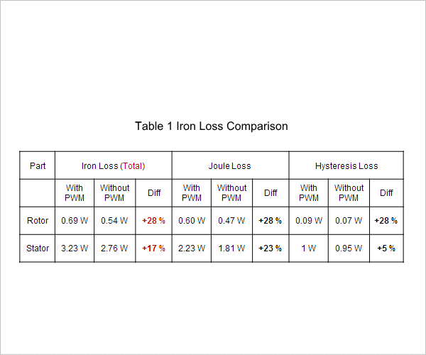
Table 1 shows the different losses in the rotor and stator iron. We can observe that the total losses in the rotor iron increased by 28 % and 17 % in the stator Iron.

