Contents
1. Introduction
2. Motor specifications
3. Relationship between table resolution and accuracy
3.1. Mechanical angle resolution dependence
3.2. Current amplitude resolution dependence
3.3. Current phase resolution dependence
4. Effect of the table resolution and time resolution on current accuracy
5. Summary
6. References
1. Introduction
In order to improve the accuracy of motor plant models, it is necessary to account for the spatial harmonics. That accuracy strongly depends on the resolution when generating the plant model, and the time resolution during execution.
This document uses JMAG-RT, which is a type of plant model, to show the relationship between the resolution and accuracy of each axis (mechanical angle, current amplitude, and current phase) of the inductance and flux linkage tables. In addition, the relationship between the time interval width and accuracy when running JMAG-RT analysis is also shown.
2. Motor specifications
The model to be used is shown in Fig. 1, which is an interior permanent magnet synchronous motor. The number of poles is 8, the number of slots is 48. The operating points used for evaluation is three points: low-speed high-torque, medium-speed medium-torque, and high-speed low-torque. The respective rotation speed and torque are shown in Table 1.
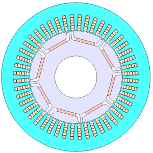
Fig. 1 Verification motor shape
Table 1 Operating points
| Point | Rotation speed (rpm) | Torque (Nm) |
| A | 2,000 | 250 |
| B | 3,000 | 140 |
| C | 8,000 | 75 |
3. Relationship between table resolution and accuracy
The inductance and flux linkage table consists of three axes of the mechanical angle, current amplitude, and current phase. In this section, the resolution of each axis is changed at the operating points A, B, and C, and the current value when running JMAG-RT is compared with that of FEA(*). Table 2 shows the table with the highest resolution where the difference with FEA is 1 % or less for any of the axes. The resolution of two axes other than the axis to be accounted for is in accordance with the settings of Table 2. In addition, the rotation angle per individual step is set in this section to 0.09 deg/step.
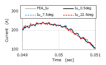 (1) Current waveforms (Point A)
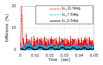 (2) Current difference (Point A)
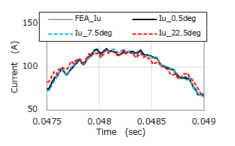 (3) Current waveforms (Point B)
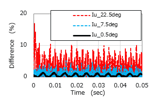 (4) Current difference (Point B)
Fig. 2 Current difference between current waveforms and FEA (mechanical angle resolution)
You need to sign in as a Regular JMAG Software User (paid user) or JMAG WEB MEMBER (free membership).
By registering as a JMAG WEB MEMBER, you can browse technical materials and other member-only contents for free.
If you are not registered, click the “Create an Account” button.
Create an Account Sign in


