Overview
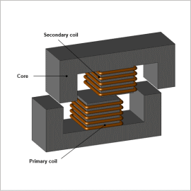
When evaluating the properties of a transformer whose primary and secondary sides are separated by a gap, it is helpful to use magnetic field analysis based on the finite element method (FEM), which allows precise modeling of the geometry of the parts and their relative positions, and makes it possible to visualize the leakage in the magnetic flux that is generated in the primary side and transmitted to the secondary side.
In this example, how to obtain the power transmission efficiency when the feeder wire’s position is moved in both the horizontal and vertical directions from a reference position, and how to display the flow of magnetic flux.
Vertical Distance vs. Power Transmission Efficiency
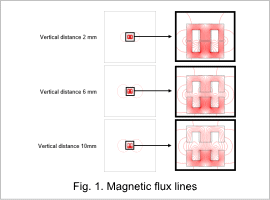
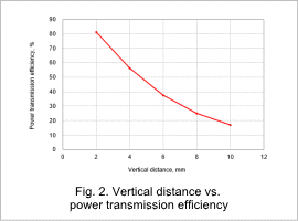
Magnetic flux density distributions with varied vertical distance between the primary and secondary sides are shown in Fig. 1, and the vertical distance versus power transmission efficiency curve is shown in Fig. 2. The leakage flux increases and the magnetic flux inside the secondary side core falls with greater vertical distance, as indicated in Fig. 1. Approximately 80% of maximum efficiency can be achieved when the vertical distance is 2 mm, as indicated in Fig. 2. The efficiency falls basically linearly because the reduction in flux linkage in the secondary coil is caused simply by the increase of the vertical distance.
Horizontal Distance vs. Power Transmission Efficiency
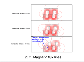
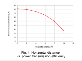
Magnetic flux density distributions with a vertical distance of 2 mm and varied horizontal distance between the primary and secondary sides are shown in Fig. 3, and the horizontal distance versus power transmission efficiency curve is shown in Fig. 4. As indicated in Fig. 3, magnetic flux in the left side of the secondary side core falls with horizontal distance, and a flow channel that does not link the secondary coil is formed when the horizontal distance is 10 mm. The efficiency is reduced nonlinearly, as shown in Fig. 4. This is because the reduction in linkage flux in the secondary coil is due not only to distance, but also to changes in the way the magnetic flux flows.
