Overview
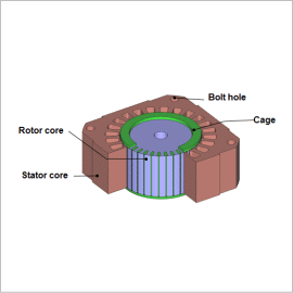
In an induction motor, the current induced by the auxiliary conductor exerts a large influence on its characteristics. It also causes strong magnetic saturation in the vicinity of the gap, in particular. This is why a magnetic field analysis based on the finite element method (FEM) is useful when investigating the motor’s characteristics for a design study.
This Application Note introduces a case example that obtains the Slip-Torque curve, Torque-Current curve, Current-Voltage curve at maximum torque, and the Current-Joule Loss curve for the cage.
Torque Characteristics
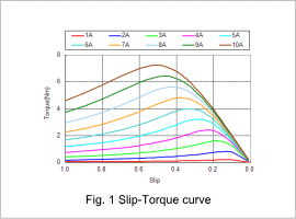
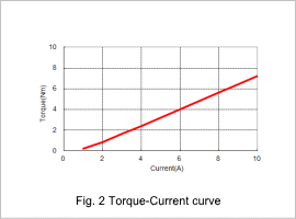
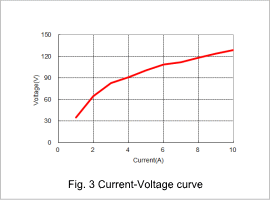
The Slip-Torque curves for each current amplitude are shown in fig. 1, the Torque-Current curve is shown in fig. 2, and the Current-Voltage curve is shown in fig. 3. As shown in fig. 1, the slip where the torque reaches its maximum value changes depending on the size of the current amplitude. The slip where the torque reaches its maximum value is determined by the coil’s electric resistance, the cage’s electric resistance, and the leakage reactance. Therefore, the changes in the leakage reactance due to an increase in current cause the changes in the slip where the torque reaches its maximum value. As can be seen from the slope of the Torque-Current curve in fig. 2, the torque constant of this induction motor is about 0.8 Nm/A. There is also a limit on the primary voltage that can be supplied, so the Current-Voltage curve needs to be used to investigate the primary voltage during maximum torque ahead of time.
Eddy Current Density Distribution/Joule Loss
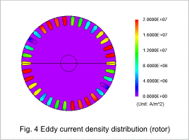
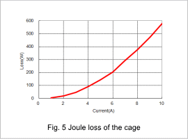
The eddy current density distribution when the current amplitude is 10 A is shown in fig. 4, and the joule loss in the cage for each current value is shown in fig. 5. Both of these are results at maximum torque. As shown in fig. 4, an excessive current with current density of over 2×10⁷ A/m2 flows through the bars, and the heat generation is large, so continuous operation is difficult. As shown in fig. 5, the joule loss increases quadratically against the current value. By estimating the heat generation from the loss, it is possible to understand the period of time when continuous operation is possible at the maximum torque. In this way, it is necessary to understand the current and losses in the cage when studying the maximum torque in a cage induction motor.
