Overview
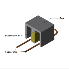
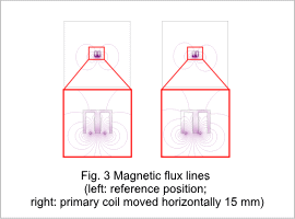
When evaluating the properties of a transformer whose primary and secondary sides are separated by a gap, it is helpful to use magnetic field analysis based on the finite element method (FEM), which allows precise modeling of the geometry of the parts and their relative positions, and makes it possible to visualize the leakage in the magnetic flux that is generated in the primary side and transmitted to the secondary side.
This Application Note presents how to obtain the power transmission efficiency when the feeder wire’s position is moved in both the horizontal and vertical directions from a reference position, and how to display the flow of magnetic flux.
Vertical Distance vs. Power Transmission Efficiency
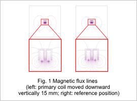
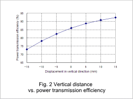
Diagrams of the magnetic flux lines with the feeder wire moved in the vertical direction are shown in fig. 1, and the power transmission efficiency is shown in fig. 2. As the distance between the feeder wire and the core gets larger, the amount of leakage flux increases and the linkage flux in the secondary coil decreases. In this way, the power transmission efficiency is reduced.
Horizontal Distance vs. Power Transmission Efficiency
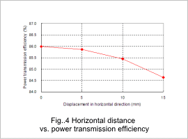
Diagrams of the magnetic flux lines with the feeder wire moved in the horizontal direction are shown in fig. 3, and the power transmission efficiency is shown in fig. 4. When the feeder wire is moved horizontally from the reference position, the balance of magnetic flux in the core becomes distorted to the left and right. Variations in the linkage flux in the secondary coil are small, and variations in power transmission efficiency are also small.
