Within increasing demand for even higher efficiency and power in motor development, there is also the increase in demand for thermal design from electromagnetic design engineers.
- Electromagnetic design must be able to suppress the temperature of the windings within the upper temperature limit that is determined for each insulation class
- Electromagnetic design and thermal design must be able to keep the magnet temperature below the upper limit of the required power
- Electromagnetic design and thermal design must be able to be run at the same time to satisfy the upper temperature limit
- An electromagnetic design engineer must be able to evaluate these quickly, even if they are qualitative evaluations
A thermal design method that balances both accuracy and ease of use is required in the electromagnetic design stage.
 JMAG Thermal Modeling Manual (PDF, 2.30MB: User authentication)
Getting Started with Motor Thermal Design: Thermal Analysis Made Easy for Beginners Using JMAG-Express (PDF 1.43 MB)
JMAG Thermal Modeling Manual (PDF, 2.30MB: User authentication)
Getting Started with Motor Thermal Design: Thermal Analysis Made Easy for Beginners Using JMAG-Express (PDF 1.43 MB)

Simultaneous Evaluation of Electromagnetic Design and Thermal Design
JMAG simultaneously evaluates both magnetic and thermal properties by sharing design variables between magnetic field analysis models and thermal analysis models.
Design variables such as dimensions and the number of poles and slots, etc., can be simultaneously reflected in both magnetic field models and thermal models for design investigations.
Motor topology: Number of poles and slots, geometry
Materials: Magnet types, core grades, windings
Power supplies: Winding settings, drive types, current vectors, control methods
Cooling: Thermal resistance between parts, cooling types, coolant properties, coolant flow velocity, etc.
Obtained magnetic properties and thermal properties can be checked on a single screen.
You can run multifaceted evaluations of torque (driving force), properties, efficiency, electromagnetic force distribution, loss, and temperature at rated operation.
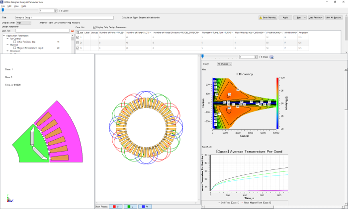
A list of design variables can also be checked at the same time. This makes it easy to repeat evaluations such as using efficiency maps to check the temperature during maximum power, and if part temperature is too high, changing the design variable values and checking the efficiency maps and temperature again.
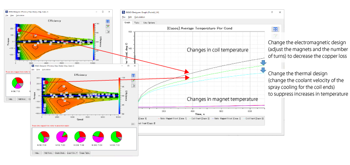
Decrease the copper loss while still satisfying the required torque and reduce the increase in temperature for the coils
Support for Thermal Resistance and Cooling Methods
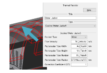
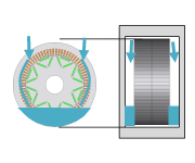
Water jacket
Spray
ATF
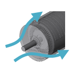
Forced convection
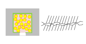
Contact resistance
These cooling methods are modeled in a thermal equivalent circuit.
Simply by entering the design parameters, such as the coolant flow velocity, geometry dimensions, and contact states, etc., the thermal resistance of the equivalent circuit is automatically calculated based on a database of CFD and actual measured values. The thermal circuit and the boundary conditions of the motor that include these thermal resistor components are also generated automatically.
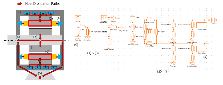
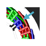
Example of motor heat dissipation paths and an actual thermal equivalent circuit (Cooling method: water jacket + spray cooling)
Convective heat transfer in the gap parts, heat dissipation accounting for contact resistance between the housing and the core, heat dissipation from the core due to the water jacket, heat dissipation from the housing, heat dissipation from the rotor core through the shaft, heat dissipation by natural convection from the core surface, and heat dissipation from the coil due to spray on the coil end parts, etc., are accounted for.
The cooling effects of each cooling type are accounted for as thermal resistance.
Workflow
1. Selecting the motor type and scenario
- Select the motor type and evaluation items from the motor type and scenario selection
- Motor types include brushless motors with typical magnet arrangements (inner rotors/outer rotors), as well as induction motors
- Characteristics evaluation can be selected from magnetic and thermal properties
2. Setting the design variables
- The number of poles and slots for the motor, geometry, drive conditions, and cooling types, etc., are listed
- Change the design variables as needed to determine the initial motor design plan
3. Running the analysis
- FEA analysis is run for both the magnetic and thermal properties
- There is no need to set any conditions or create the mesh required for the FEA analysis
4. Checking the motor characteristics
- You can check the magnetic properties such as the torque and efficiency maps, and thermal properties such as temperature history, etc., via the graphs and contours
5. Parametric evaluation
- When requirements are met or not met, or when we want to find designs with better properties, change the design variables while continuing to look at the sensitivity and the properties
- Multiple design plans can be analyzed simultaneously. This means that you can evaluate various design plans in a short amount of time
6. Concept design completion
- Proceed to a more detailed design based on the design plan that meets the requirements of the concept design
- All the models used in the workflow up until this point, including the condition settings and the geometry, have been saved in JMAG-Designer. Using this as a starting point, we can then proceed to more detailed design, such as AC loss analysis that includes the coil ends, and creating efficiency maps that account for control

