Overview
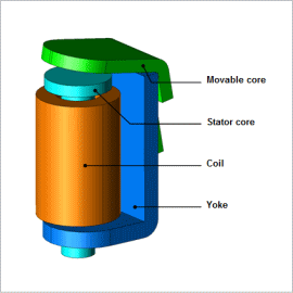
To put it simply, the attractive force is determined from the area of the gap between the movable core and the stator core and the size of the magnetic flux density produced in said gap. With a relay whose movable core does not move linearly, however, it is a difficult problem to predict the magnetic flux density in the gap because it does not become parallel. The nonlinear magnetic properties of the iron core and yoke also affect the magnetic flux density in the gap. With a JMAG magnetic field analysis, it is possible to obtain the attraction force of the movable core while accounting for these factors. One of the reasons that the response is delayed in electromagnetic relays is eddy currents, which are produced when the magnetic flux generated by current flow undergoes time variations. The eddy currents are generated in a direction that inhibits changes in the magnetic flux, causing a delay in the initial rise of the attraction force when the current begins to flow. This reduces the injector’s responsiveness. JMAG makes it possible to account for the effects from eddy currents and obtain an electromagnetic relay’s responsiveness by running a transient response analysis.
This Application Note presents the use of the motion equation function to evaluate the operating time of an electromagnetic relay with DC voltage drive. Eddy currents generated in the core are considered for this purpose.
Operating Time
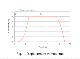
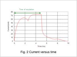
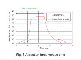
The displacement versus time is indicated in fig. 1, the current versus time is indicated in fig. 2, and the attraction force versus time is indicated in fig. 3.
The current gradually increases after excitation starts, but it does not increase easily for around 2 ms because of the reverse electromotive force that comes with an increase in magnetic flux. Even after the excitation stops at 5 ms, the movable core still contacts the stator core because of the electromagnetic energy stored in the coil flowing through the diode, but when the elastic force of the spring becomes stronger than the attractive force at around 7 ms, the movable core returns to its initial position.
Magnetic Flux Density Distribution
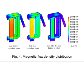
After excitation stops, the magnetic flux density decreases gradually because current is still flowing into the coil through the diode due to the effect of the electromagnetic energy in the coil as indicated in fig. 2.


