Overview
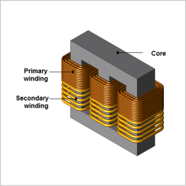
Using finite element analysis (FEA) to confirm the distribution of iron loss density makes it possible to study a transformer’s local geometry during design. Further, evaluating the ratio and distribution of the iron and copper losses through FEA becomes advantageous when designing a transformer.
This note presents how to obtain the iron and copper losses of a three-phase transformer.
Iron loss Density Distribution
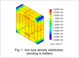
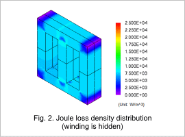
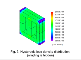
The iron loss density distribution of the core is shown in fig. 1, the joule loss density distribution of the core in fig. 2, and the hysteresis loss density distribution of the core in fig. 3. From fig. 1, it is apparent that iron losses increase in the inside corners. This is because the magnetic flux flows through the shortest route of the core. As can be seen from figures 2 and 3, a large percentage of the iron loss is hysteresis loss.
Current Density Distribution and Copper Loss Density Distribution
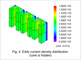
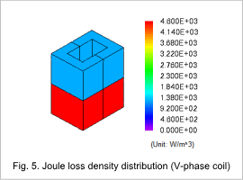
The current density distribution of the coil is shown in fig. 4, and the joule loss density distribution in fig. 5. From fig. 4, it is apparent that the current density distribution is approximately the same in each phase. Joule loss is higher in the secondary coil than the primary coil, as indicated in fig. 5. This is because the current is larger in the secondary coil.
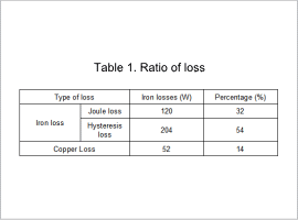
Percentage of Loss
