*Please prepare a license ID and password for the license administrator.
*It is different from the service for JMAG WEB MEMBER (free membership). Please be careful.
Overview
Voltage surges can damage the components in electrical equipment such as an inverter.
Bus bar inductance can be a cause of surges. Therefore, it is important to reduce it to protect the electrical equipment.
Using FEM allows for the calculation of inductance based on the magnetic field and current distribution obtained from the magnetic field analysis. This note presents a case study on the current distribution and the frequency versus inductance characteristic of the bus bar.
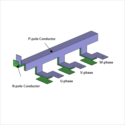
Current Distribution in the Conductor
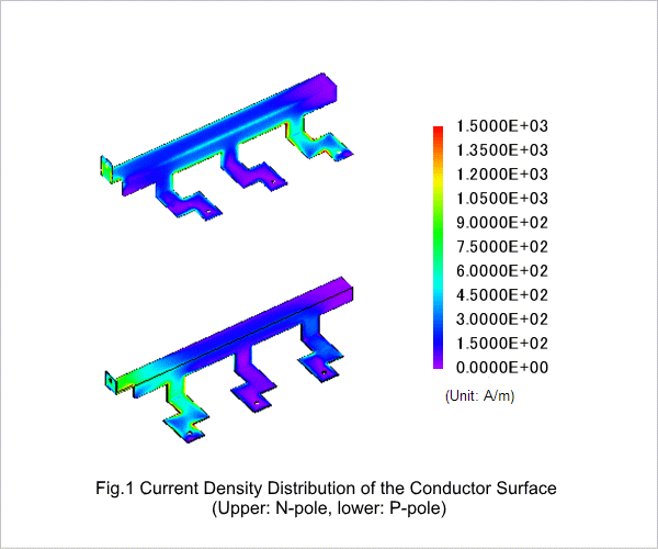
Fig.1 shows the current density distribution in the conductor when applying the current from +U phase to -W phase.
This current distribution is caused by the skin effect in which the current concentrates near the surface. This current distribution affects resistance and inductance.
This current distribution is caused by the skin effect in which the current concentrates near the surface. This current distribution affects resistance and inductance.
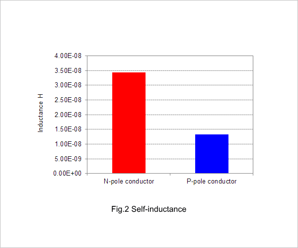
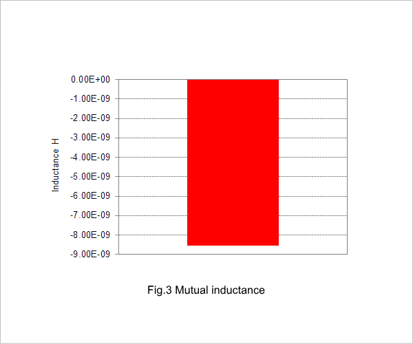
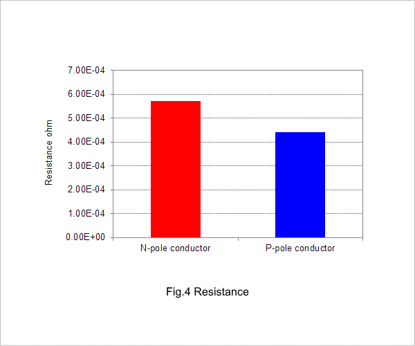
Inductance
Fig. 2 shows self inductance of the N and P pole conductors, Fig. 3 shows the mutual inductance between the N and P pole conductors, and Fig. 4 shows the Resistance of the N and P pole conductors.