*Please prepare a license ID and password for the license administrator.
*It is different from the service for JMAG WEB MEMBER (free membership). Please be careful.
Overview

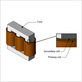
A transformer is an electrical device that uses electromagnetic induction to convert the voltage level of alternating current power. Electromagnetic force is produced by the current and magnetic field in a transformer’s coils while it is converting power. There is a risk that a large electromagnetic force can cause the coils to deform or rupture, particularly when something goes wrong and current flows in a short circuit.
Electromagnetic force is produced by the current and magnetic field in a coil, but the coil is exposed to not only the magnetic field it produces by itself but also the magnetic field from other coils and leakage flux from the core. Because of this, it is important to evaluate in advance what kinds of forces are produced in what areas due to the arrangement of the coils and the positional relationship of the coils and core using magnetic field analysis.
This analysis uses different coil positions to evaluate the Lorentz force density and electromagnetic force produced in the coils during a short circuit in order to confirm the effects that the primary and secondary coils have on each other.
Lorentz Force Density
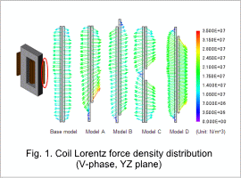
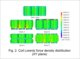
The Lorentz force density distribution vectors of the V-phase coil as seen from the X-axis are shown in fig. 1, and the Lorentz force density distribution vectors of the three phases as seen from the Z-axis are shown in fig. 2. From fig. 1, it can be seen that the direction of the force working on the coil varies according to how the coils are wound. Fig. 2 indicates that in models A and D, in which the deviation of the Lorentz force is large, the Lorentz force density to the inside grows large because it is influenced by the adjacent coils.


Electromagnetic Force

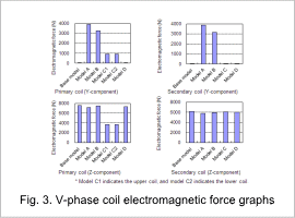
The electromagnetic force of the V-phase coil is shown in fig. 3. The Z-component graph shows that, in all of the models, repulsion force is produced that mutually separates the primary and secondary coils. In an actual machine, the Z-component force is canceled out by symmetry, but this force can be seen in analysis because only a half model is used.
From the Y-component graph, it can be seen that a greater force is working in models A and B compared to the other models. When the balance of the coil’s winding method is asymmetrical vertically, a large force is produced in the vertical direction in addition to the repulsion in the radial direction, as indicated by the Lorentz force density vectors in fig. 1. The overall force in model D is canceled out so its Y-component force is zero, but by looking at the Lorentz force density vector distribution, it can be seen that force is produced a direction that compresses the primary coil as a whole.
From the Y-component graph, it can be seen that a greater force is working in models A and B compared to the other models. When the balance of the coil’s winding method is asymmetrical vertically, a large force is produced in the vertical direction in addition to the repulsion in the radial direction, as indicated by the Lorentz force density vectors in fig. 1. The overall force in model D is canceled out so its Y-component force is zero, but by looking at the Lorentz force density vector distribution, it can be seen that force is produced a direction that compresses the primary coil as a whole.


