Overview
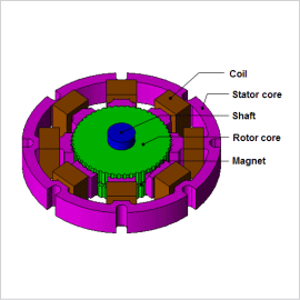
The two-plated rotor core of a stepper motor has an N pole on one side and an S pole on the other, so a multipole magnet is achieved by deviating the saliency of the gear condition by 1/2 pitch. Consequently, the magnetic circuit is 3D. There are also times when the division pitch geometry of the teeth is complicated, so it is necessary to carry out a 3D electromagnetic field analysis using the finite element method (FEM) to proceed with an accurate preliminary study.
This document introduces how the detent torque and stiffness torque can be calculated for a hybrid stepper motor.
Detent Torque
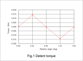
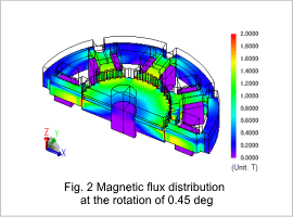
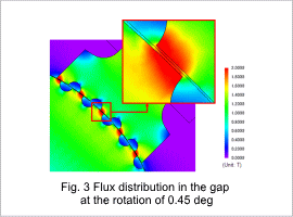
The detent torque is shown in fig. 1, and the magnetic flux distribution in the XY-plane at the rotation position of 0.45 degrees is shown in fig. 2. A closer view to show the flux distribution in the gap is shown in fig. 3. These results reveal that the flux in both the rotor and stator is saturated even with no excitation. The flux leakage around the tips of the teeth, due to saturation, can be expected to have a large effect on the detent torque.
Stiffness Torque
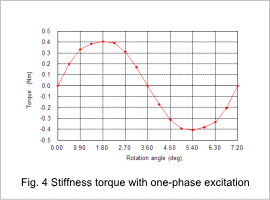
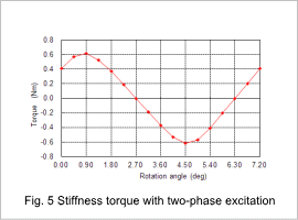
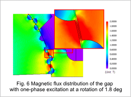
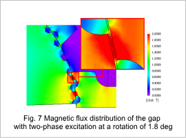
Fig. 4 shows the stiffness torque with one-phase excited and fig. 5 shows the stiffness torque with two-phase excited. The flux distribution in the gap of the XY-plane with one-phase excited is shown in fig. 6, and the flux distribution in the gap of the XY-plane with two-phase excited is shown in fig. 7. As with the detent torque, the magnetic flux around the teeth is saturated. The flux leakage caused by the saturation can be expected to also have a large effect on the stiffness torque.
