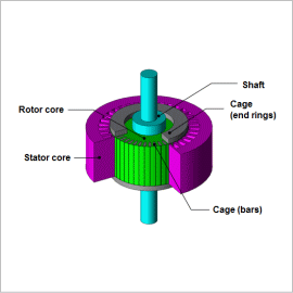
[JAC176] Drive Characteristic Analysis of a Three-Phase Induction Motor

Sign in to download the data

Sign In

*Please prepare a license ID and password for the license administrator.
*It is different from the service for JMAG WEB MEMBER (free membership). Please be careful.
About authentication ID for JMAG website

Overview

Drive Characteristic Analysis of a Three-Phase Induction Motor
An induction motor is a motor in which the rotating magnetic field of the stator coils causes induced current to flow in an auxiliary conductor, which exerts force on the rotor in the rotational direction and causes it to spin. Induction motors are widely used in everything from industrial machines to home appliances because they have a simple construction and are small, light, affordable, and maintenance-free.
In an induction motor, the current induced by the auxiliary conductor exerts a large influence on its characteristics. It also causes strong magnetic saturation in the vicinity of the gap, in particular. This is why a magnetic field analysis based on the finite element method (FEM) is useful when investigating the motor’s characteristics for a design study.
This Application Note explains how to confirm drive characteristics such as torque, loss, and efficiency in an induction motor when its rotation speed changes.

Drive Characteristics (Voltage Control)

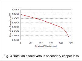
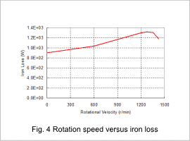
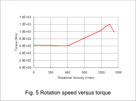
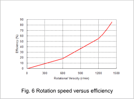
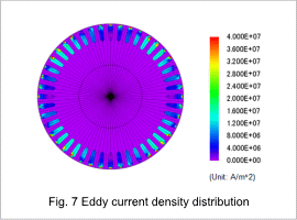
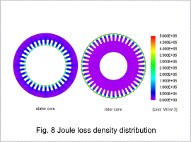
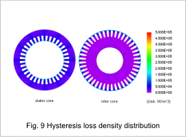
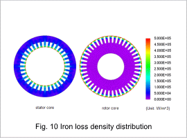
The primary current, primary copper loss, secondary copper loss, iron loss, torque, and efficiency with changing rotation speeds during voltage control are shown in figures 1 through 6. The eddy current density distribution, joule loss density distribution, hysteresis loss density distribution, and iron loss distribution at maximum efficiency are shown in figures 7 through 10.
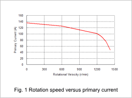
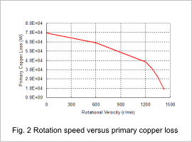
Fig.1 Rotation speed versus primary current
Fig.2 Rotation speed versus primary copper loss
Fig.3 Rotation speed versus secondary copper loss
Fig.4 Rotation speed versus iron loss
Fig.5 Rotation speed versus torque
Fig.6 Rotation speed versus efficiency
Fig.7 Eddy current density distribution
Fig.8 Joule loss density distribution
Fig.9 Hysteresis loss density distribution
Fig.10 Iron loss density distribution

Drive Characteristics (Current Control)

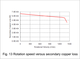
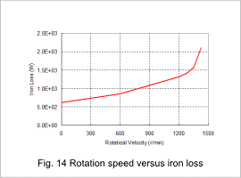
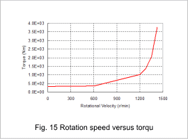
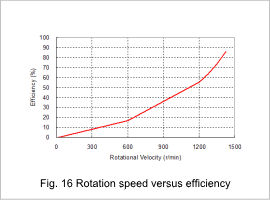
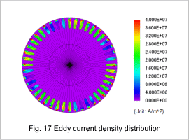
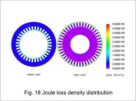
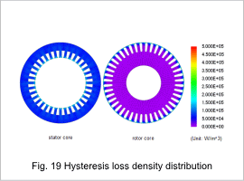
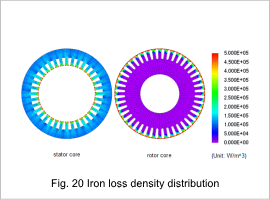
The primary voltage, primary copper loss, secondary copper loss, iron loss, torque, and efficiency with changing rotation speeds during current control are shown in figures 11 through 16. The eddy current distribution, joule loss density distribution, hysteresis loss density distribution, and iron loss distribution at maximum efficiency are shown in figures 17 through 20.
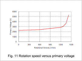
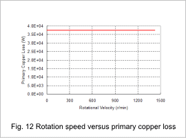
Fig.11 Rotation speed versus primary voltage
Fig.12 Rotation speed versus primary copper loss
Fig.13 Rotation speed versus secondary copper loss
Fig.14 Rotation speed versus iron loss
Fig.15 Rotation speed versus torque
Fig.16 Rotation speed versus efficiency
Fig.17 Eddy current density distribution
Fig.18 Joule loss density distribution
Fig.19 Hysteresis loss density distribution
Fig.20 Iron loss density distribution

Search Filter

  • All Categories