Overview
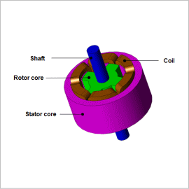
SR motors create their excitation state by alternating between opening and closing switches in accordance with the position of the rotor’s rotation, however the timing of the alternating causes major changes in the torque properties. Also, it is important not only to increase the torque average and torque constant, but also to consider the optimum switch timing to control vibration and noise.
This example presents how to carry out an analysis with different switch timings to evaluate torque and current in SR motors.
Torque Waveform
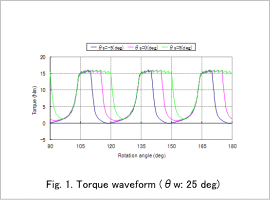
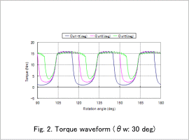
The torque waveform for each voltage application width θw with changing the voltage application start angle θs are shown in fig .1 and fig .2.
By changing θs and θw, we understand that the torque waveform has changed.
Current Waveform
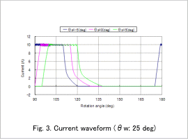
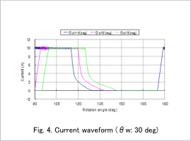
The current waveform of the A-phase coil for each voltage application width θw with changing the voltage application start angle θs are shown in fig. 3 and fig. 4.
It is apparent that if the θw is 30 deg, it takes a longer time for the current to decrease to 0A. This is because the rotor tooth is nearing the stator and inductance has increased.
Copper Loss Waveform
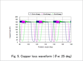
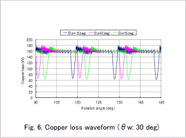
The copper loss waveform for each voltage application width θw with changing the voltage application start angle θs are shown in fig. 5 and fig. 6.
It is apparent that depending on the voltage application width, there is a large difference in the waveform. We can understand that if θw is 30 deg, copper loss is bigger in the range of multiple phase currents flowing simultaneously.
Switching Properties
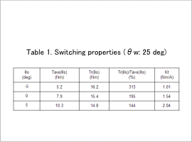
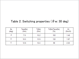
The average torque Tave(θs), torque ripple Tr(θs), torque ripple rate Tr(θs)/Tave(θs), and torque constant Kt for each voltage application width θw with changing the voltage application start angles are shown in table 1 and table 2.
In this case, average torque and torque constant are at a maximum and the torque ripple rate is at a minimum at θw = 30 deg, θs = 5 deg. It is possible to consider optimum switch timing in accordance with required specifications.
