*Please prepare a license ID and password for the license administrator.
*It is different from the service for JMAG WEB MEMBER (free membership). Please be careful.
Overview
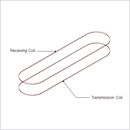
Originally there were only two types of wireless power transfer systems: proximity and long distance. However, recently mid-distance devices have been developed and has it made it possible for highly-efficient power transmission even when the transmission and receiving end are disconnected. Although there are charging devices for cellular phones that have already been released as products, research of charging large products such as automobiles and machine tools is currently in the process.
This document introduces the procedure in obtaining the optimum solution for geometries of transmission coils (angle that defines position) for simple magnetic resonance wireless power transfer system. Even if you are a user of applications excluding wireless power transfer systems, please use this document as a function reference material to get a grasp of the optimization procedure and the flow of result evaluation.
This document introduces the procedure in obtaining the optimum solution for geometries of transmission coils (angle that defines position) for simple magnetic resonance wireless power transfer system. Even if you are a user of applications excluding wireless power transfer systems, please use this document as a function reference material to get a grasp of the optimization procedure and the flow of result evaluation.
Efficiency
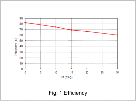
Fig. 1 shows the efficiency relative to the tilt calculated in optimization.
This shows that efficiency is decreasing as the tilt gets bigger.
This shows that efficiency is decreasing as the tilt gets bigger.
Coupling Coefficient
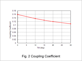
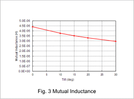
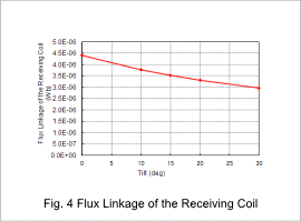
If the coupling coefficient, which is the coupling level of the transmission coil and the receiving coil, becomes poor, it will also decrease efficiency. The coupling coefficient in relation to the tilt is shown in fig. 2. The coupling coefficient will get smaller as the tilt gets larger. Fig. 3 shows the mutual inductance in relation to the tilt. It can also be confirmed that as the tilt gets larger, mutual inductance drops as well. This is because flux linkage to the receiving coil decreases, as shown in fig. 4.
Magnetic Flux Lines
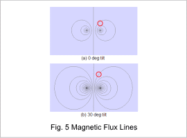
Fig. 5 shows the magnetic flux line at 0 deg and 30 deg as the tilts of receiving coil. The magnetic flux line is displayed at 90 deg for phase settings, where transmission coil current will be the maximum value.
The receiving coil where tilt occurs has been marked with a circle. When comparing 0 deg and 30 deg, the coil at 30 deg is outside the flux line. For this reason, the magnetic flux that links to the receiving coil drops. It can be said that adjusting parameters such as capacitance is required when creating models with tilts.
The receiving coil where tilt occurs has been marked with a circle. When comparing 0 deg and 30 deg, the coil at 30 deg is outside the flux line. For this reason, the magnetic flux that links to the receiving coil drops. It can be said that adjusting parameters such as capacitance is required when creating models with tilts.


