Overview
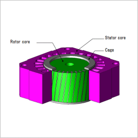
Generally when skew is applied, magnetic flux also flows in the axis direction, and this requires that a 3D analysis is performed in order to thoroughly evaluate skew effect. However, 3D analyses tend to cause an inordinate amount of calculation costs. The multi-slice method, representing skew approximately with a 2D cross-section superimposition, is effective.
In this document, the multi-slice method is used to compare torque waveforms of a cage three-phase induction motor with and without skew, and is then used to verify the effects of using skew to reduce torque variations.
Torque Characteristic
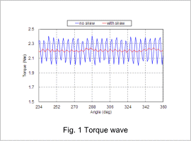
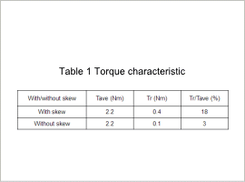
The torque waveform is indicated in fig. 1, and the torque characteristics are indicated in table 1.
The harmonics of torque are significantly deleted due to skewing, showing that this is connected to a decrease in vibration and noise.
Current in the Secondary Conductor
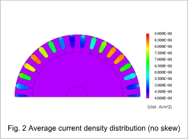
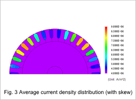
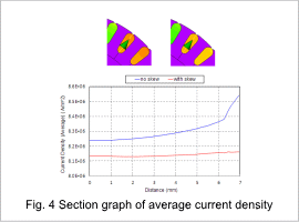
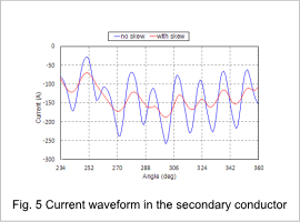
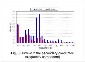
Average current density distribution in one period of electric angle in the secondary conductor is shown in fig. 2 and 3, a section graph is shown in fig. 4, and current waveform and frequency components for the secondary conductor are shown in fig. 5 and 6.
As shown in fig. 2, 3 and 4, bar current without skewing is concentrated on the rotor surface, and with skewing, bar current enters almost to the inside. As shown in fig. 5 and 6, it is believed that this is due to the harmonic components in the secondary current decreases due to skewing, and the skin depth then becomes thicker. Slot harmonic components around 420(Hz), determined by the number of revolutions and slots, are greatly reduced.
