*Please prepare a license ID and password for the license administrator.
*It is different from the service for JMAG WEB MEMBER (free membership). Please be careful.
Overview
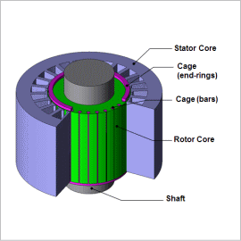
Since single phase induction motors can be used with single-phase AC, which is common in general household power supply, it is widely used for electrical home and office appliances such as washers and fans as small power motors. However, unlike three-phase AC, single phase AC cannot independently create a rotational magnetic field, and since it cannot run a motor at this state, there is a need to develop a rotational magnetic field somehow and make it run.
Characteristics of single phase induction motors are affected by factors such as the secondary side and leakage inductance. These are called equivalent circuit parameters and they are important because they characterize the device’s properties. Equivalent circuit parameters are greatly affected by current distribution induced by secondary conductors and magnetic saturation near the gap, and accurately understanding these characteristics using finite element analysis will be required.
In this document, we will be obtaining the secondary resistance, leakage inductance and excitation inductance of main winding of capacitor-start single-phase induction motor that has auxiliary winding.
Equivalent Circuit Parameter
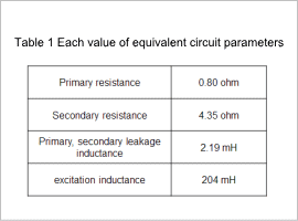
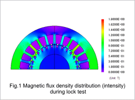
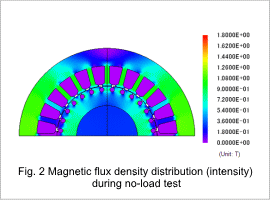
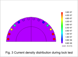
The equivalent circuit parameter of 100V voltage and frequency 50Hz will be shown in fig. 1. In addition, the magnetic flux density (intensity) distribution of lock test analysis is shown in fig. 1, and the magnetic flux density (intensity) distribution of no-load test analysis in fig.2. Fig. 3 will show the current density (intensity) distribution of the lock test analysis bar.
