*Please prepare a license ID and password for the license administrator.
*It is different from the service for JMAG WEB MEMBER (free membership). Please be careful.
Overview
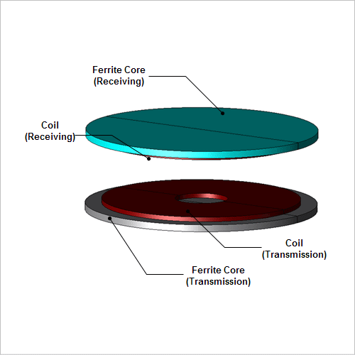
In recent years, electromagnetic induction type transmission is considered for applied use in wireless power supply systems for electric vehicles (hereinafter, referred to as EV) and plug-in hybrid cars (hereinafter, referred to as PHEV), which are demanded for practical use. As for wireless power supply systems for EV / PHEV, even if the car-equipped coil of the receiving end and the ground buried coil of the transmission end slip out of place in the horizontal position, electric power transmission needs to be retained with high efficiency. Recently, circuits with excitation condensers, which retain a large power supply of electric power is also considered.
Efficiency changes, which is triggered by change of positioning, is primarily because of the change in magnetic flux in the receiving end where the transmission coil is slightly shifted in relation to the receiving coil. Furthermore, run magnetic field analysis when evaluating power supply of electric power or capturing the variations in spatial magnetic flux.
This example presents, an electromagnetic induction-type wireless power supply system using an excitation circuit positioned with a parallel resonance condenser on the receiving end, and a series resonance condenser on the transmission end will be analyzed. An efficiency change in relation to the disposition in the horizontal direction is evaluated from both power transmission efficiency and the coupling coefficient.
Power Value / Power Transmission Efficiency
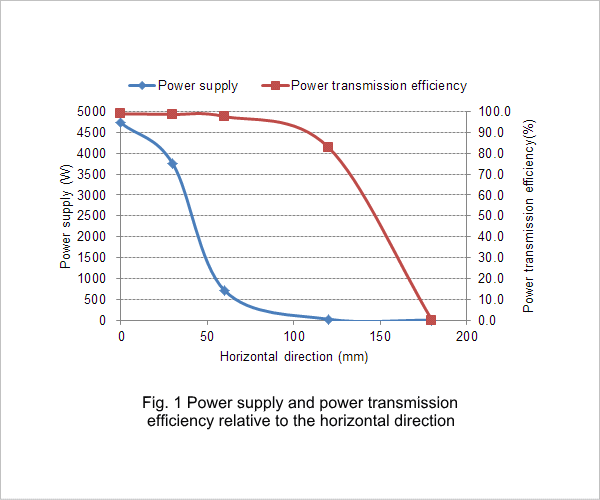
Graphs of power value and power transmission efficiency when changing the horizontal distance between the transmission and receiving coils are shown in Fig. 1.
When there are no displacements in the horizontal direction, power close to 4.7kW can be obtained with a maximum efficiency of 99%. The state where both the transmission and receiving coil centers match up is considered 0, and the distance that it moves in the horizontal direction (horizontal distance) is defined as displacement in the horizontal direction. As the horizontal distance between the transmission and receiving coil gets larger and displaced, both power supply and power transmission efficiency will decrease. Power transmission efficiency / power value will both be 0 at 180mm.
Since voltage of the transmission coil is constant in this model, the input voltage will change. Reduction of power value is thought to be because of the circuit design. With displacement in the horizontal direction, self-inductance of the coil will not change, but there will be a change in mutual inductance between coils. This causes the resonance frequency determined by the inductance and capacitor to be displaced, and power transmission efficiency will drop.
Coupling Coefficient
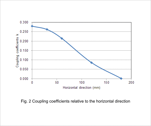
Fig. 2 shows the coupling coefficient when the horizontal distance between transmission and receiving coils is changed.
As with coupling coefficients, it will drop due to displacements in the horizontal direction.
As with coupling coefficients, it will drop due to displacements in the horizontal direction.
Magnetic Flux Density
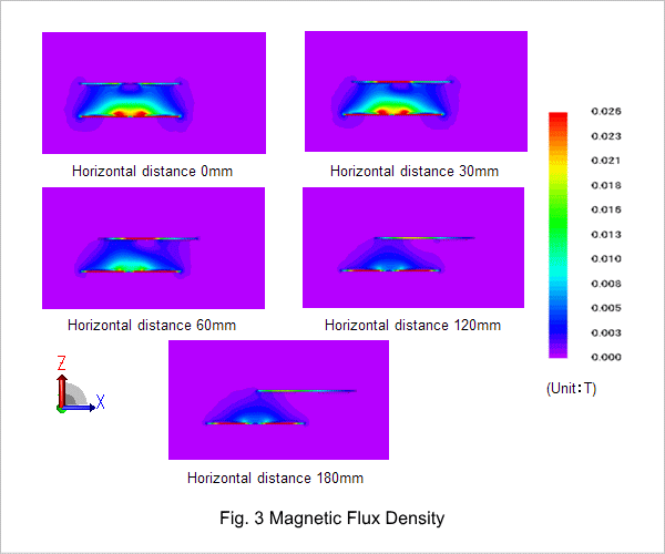
Fig.3 shows the magnetic flux density distribution when the horizontal distance is changed between the transmission and receiving coils. As horizontal distance changes, magnetic flux linked to the receiving coil (above) decreases. It is possible to confirm that these changes in flow of magnetic flux are the cause of decrease in power supply, efficiency, and coupling coefficient.

