Overview
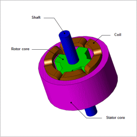
The magnetic flux density waveform in each part of the SR motor is in a state where direct current magnetic flux is superimposed on the alternating current magnetic flux. Direct current bias magnetism, like in this case, has confirmed that the iron loss analysis method using the conventional Steinmetz empirical law produces underestimated evaluations of loss.
This example, to accurately capture iron loss that occurs in the SR motor, we will introduce hysteresis loss accounting for the hysteresis loop of the materials and the iron loss analysis methods accounting for eddy current loss on the inside of the lamination cross section.
Iron Loss
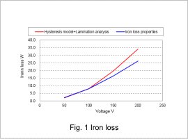
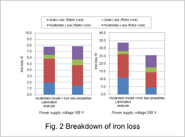
Fig.1 shows the obtained iron loss value, and Fig. 2 shows the breakdown of hysteresis loss and joule loss of the rotor and stator. It is comparing with the analysis using the original iron loss properties. For more information about setting iron loss calculation using iron loss properties, see “JAC181 Analysis of SR Motor Drive Characteristics.” It is confirmed that iron loss increases as power supply voltage gets larger. By using the hysteresis model and lamination analysis, larger iron loss is obtained from the iron loss properties, and as supply voltage gets large, the difference also increases. At 200V, a value higher by approximately 30% than the original iron loss properties is estimated. It can be confirmed that the hysteresis loss is largely increased in a hysteresis model although joule loss drops in the lamination analysis, when confirming the breakdown of iron loss at voltage of 100V to 200V.
Iron Loss Density Distribution
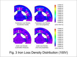
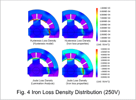
Fig.3 shows the iron loss distribution at supply voltage of 100V, and Fig.4 shows the iron loss distribution at 200V. It can be confirmed that hysteresis loss density is high at the corner of the salient pole part of the rotor and stator in a hysteresis model. The density of joule loss is also high at the corner of the salient pole part, but the joule loss of iron loss properties is high.
