*Please prepare a license ID and password for the license administrator.
*It is different from the service for JMAG WEB MEMBER (free membership). Please be careful.
Overview
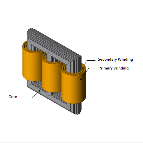
Stray loss is mainly caused by leakage flux from winding, but structures closer to the winding will tend to be affected easier by leakage flux. The ratio of stray loss relative to all losses may not necessarily be large but heat is generated in certain areas and may become an issue in the operation of transformers. In particular, stray loss occurring in the core tends to have effect on not only the core, but insulated items that construct the core, and may result in degradation of insulating oil due to burnout.
Stray loss of the core is physically iron loss, but the cause is not the main magnetic flux in the core. Categorically, it is considered stray loss as it is evaluated from short-circuit tests in the actual machine test and because it is caused by leakage flux from the winding.
This document introduces runs analysis by modeling the short-circuit test that is conducted when evaluating stray loss and obtains stray loss distribution in the core close to the winding.
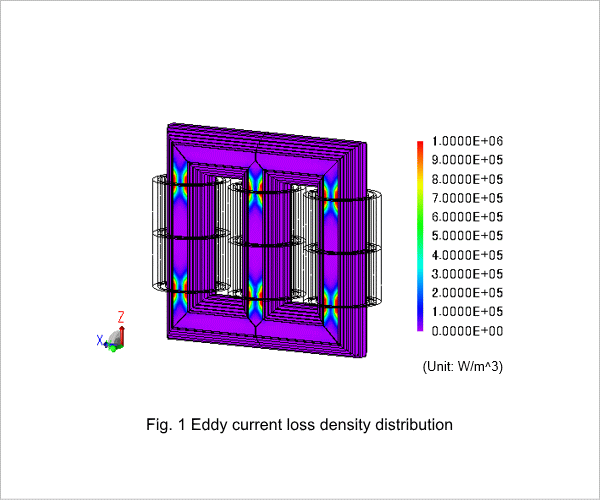
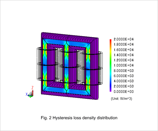
Eddy Current Loss Density Distribution, Hysteresis Loss Density Distribution
Fig.1 shows the eddy current loss density distribution of the core, and Fig.2 shows hysteresis loss density distribution. It can be seen that the effects of leakage flux from the winding ends are large.
Magnetic Flux Lines
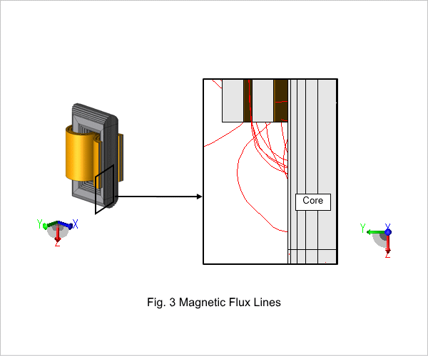
Fig.3 shows the magnetic flux lines from the center foot section direction. As this is a short-circuit test, it can assume that all occurring magnetic flux are leakage flux. It can be seen that magnetic flux that is leaking from the winding ends are almost perpendicular to the core. This occurs because the permeability inside the core differs greatly from the permeability on the outside of the core. This leakage flux causes local eddy current loss in the core surface.
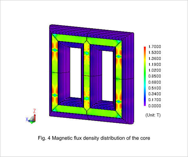
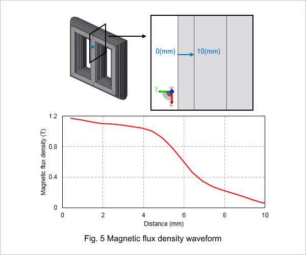
Magnetic Flux Density Distribution
Fig.4 shows magnetic flux density distribution of the core, and Fig.5 shows the current density waveform of 1 block in the lamination direction of the center foot. The block on the outermost layer of the core accounts for eddy current; therefore, with secondary magnetic flux occurring due to eddy current, magnetic flux density has become large on the steel sheet near the surface. On the contrary, as it is a short-circuit test, it can be seen the magnetic flux density is low as magnetic flux does not flow inside the core.
Eddy Current Loss Density Waveform
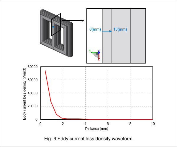
Fig.6 shows eddy current loss density waveform equivalent to 1 block of the lamination direction near the winding end part of the center foot. With the effects of leakage flux, it can be seen that there is strong heat generation on the core surface.

