*Please prepare a license ID and password for the license administrator.
*It is different from the service for JMAG WEB MEMBER (free membership). Please be careful.
Overview
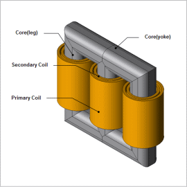
Large-scale power transformers are expected to be highly-reliable as machinery that will support the industry infrastructure, but unfortunately, it is impossible to conduct tests connecting to actual load. For this reason, tests of special circuit structure including no-load tests and contradiction tests are run.
No-load tests are tests that apply rated voltage in the primary side at the no-load state of the secondary side. Current only flows to the primary side in the no-load test, but this current causes excitation and iron loss of the iron core.
If it is an iron core that has a tripod structure, the magnetic circuit of each phase is not completely equivalent, and thus causes unbalanced current.
This example focuses on modeling in the analysis of no-load tests in JMAG and obtains the magnetic flux line, current, excitation conductance, and excitation susceptance that can be acquired from there.
Magnetic Flux Lines
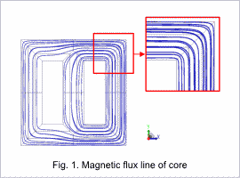
The magnetic flux line of the core is shown in Fig. 1. According to the material properties of grain oriented steel, you can see that the magnetic flux line of the core is oriented along the easy axis of magnetization.
Iron Loss Current, Magnetization Current
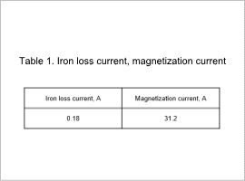
Effective values for iron loss current and magnetization current are shown in Table 1. In the three-legged iron core, the center leg and the left/right legs are not equivalent in the magnetic circuit, so unbalanced current is generated between the three phases. In Table 1, the average values are taken for the current running through the three phases.
Excitation Conductance, Excitation Usceptance
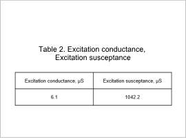
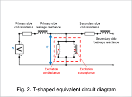
Excitation conductance and excitation susceptance are shown in Table 2, and the T-shaped equivalent circuit diagram in the transformer is shown in Fig. 2. In the no-load test, the circuit constant in the dotted lines are obtained in the equivalent circuit shown in Fig. 2. Voltage decreases due to the primary side coil resistance and the primary side leakage reactance are considered to be sufficiently small, so V’=V is assumed.
