Overview
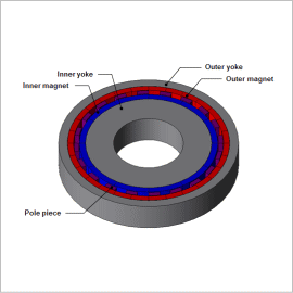
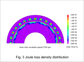
When prioritizing the size of the transfer torque, rare earth sintered magnets with high energy product are selected for permanent magnets used in magnetic gear. However, since rare earth sintered magnets have high electric conductivity (not as strong as metals such as copper though), eddy current will occur in the permanent magnet and become the cause for decrease in transfer efficiency of magnetic gear. Eddy current of permanent magnets will occur due to variations in magnetic flux density of the gap; however, due to the principle of magnetic gears using pole pieces, the magnetic flux density distribution of gaps have various harmonics components, and for this reason, magnetic field analysis is effective in accurately estimating eddy current.
In this example, the transfer torque and transfer efficiency are obtained with magnetic field analysis for the flux modulated type magnetic gear using permanent magnets for the inner and outer rotor and positioning a pole piece between the magnets. In addition, how transfer torque and transfer coefficient are affected due to revolution speed is researched.
Torque, Transfer Efficiency
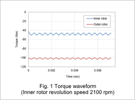
As an example of a torque waveform that works on the inner and outer rotor, the results for the inner rotor with revolution speed of 2100 (rpm) will be shown in Fig. 1. The torque is negative for both the inner and outer rotor, but as the inner rotor is forcibly rotated in the counter-clockwise direction, which is the positive direction in terms of rotation direction, it shows that external force equivalent to torque is necessary for rotation. On the contrary, the outer rotor is rotated in the clockwise direction, which is the negative rotation direction. As torque is negative, it shows that the force rotating the inner rotor is transferred as the force rotating the outer rotor.
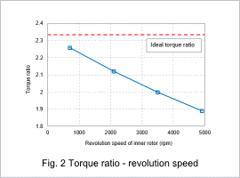
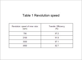
Table 1. shows the transfer efficiency from the inner rotor to the outer rotor. As it is with torque ratio, it can be seen that efficiency decreases with increase in revolution speed.
Joule Loss
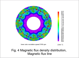
Magnetic Flux Density Distribution, Magnetic Flux Line
