*Please prepare a license ID and password for the license administrator.
*It is different from the service for JMAG WEB MEMBER (free membership). Please be careful.
Overview
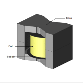
A choke coil is an electronic component aimed at filtering high frequency current. The current generated inside a choke coil has a distribution in a single wire, and among the wires, due to current bias from the skin effect, proximity effect, and leakage flux near the gap.
By using a magnetically plated copper wire with a ferromagnetic thin film layer for the coil wire, high frequency loss can be reduced compared to conventional polyurethane copper wire. This is due to the proximity effect generated in the coil being reduced by the magnetic plating layer, and due to the effective resistance of the conductor being lowered.
In this example, high frequency resistance values are obtained from choke coil copper loss analysis results using JMAG’s layer coating mesh function, and the effectiveness of reducing the resistance value of the coil using magnetically plated wire is confirmed.
Specification of Copper Wire
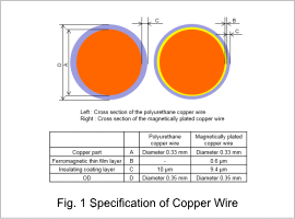
Fig. 1 shows the specification of copper wire used in this case study.
Comparisons of AC Resistance Value Frequency Characteristics
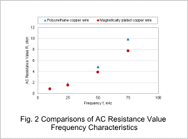
In fig. 2, the frequency resistance values from the Joule loss values of the coil when polyurethane copper wire and when magnetically plated wire are used are calculated, and the frequency resistance values at each frequency are compared.
From fig. 2, it can be seen that when using magnetically plated wire, the AC resistance is lower than when polyurethane copper wire is used.
From fig. 2, it can be seen that when using magnetically plated wire, the AC resistance is lower than when polyurethane copper wire is used.
Comparison of Copper Loss Density Distributions
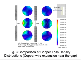
Fig. 3 show the Joule loss density distribution and isolines for polyurethane copper wire and magnetically plated wire at a frequency of 75 kHz.
From fig. 3, it can be seen that joule loss when using magnetically plated wire is lower than when using polyurethane copper wire.
This shows that there is an influence from the proximity effect of coil wire being reduced when magnetically plated wire is used.
From fig. 3, it can be seen that joule loss when using magnetically plated wire is lower than when using polyurethane copper wire.
This shows that there is an influence from the proximity effect of coil wire being reduced when magnetically plated wire is used.
Comparison of Magnetic Flux Density Distributions
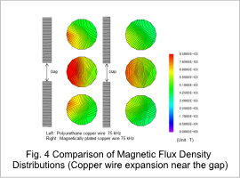
Fig. 4 shows the magnetic flux density distributions in coil wires near the gap when using polyurethane copper wire and magnetically plated wire.
The figure shows that the magnetic flux density in the copper wire when using magnetically plated wire is smaller than when using polyurethane copper wire.
As shown in the figure, when magnetically plated wire is used, the number of isolines in the copper wire is large indicating that the magnetic flux concentrates on the copper wire surface, and the difference in the magnetic flux density between the copper wire interior and surface is higher than that for polyurethane copper wire.
Since a magnetic circuit is formed around the copper wire in the magnetic layer when a magnetically plated wire is used, and since the magnetic flux generated by the proximity effect in the wire interior is lower, it is seen that this is effective in reducing current bias.


