*Please prepare a license ID and password for the license administrator.
*It is different from the service for JMAG WEB MEMBER (free membership). Please be careful.
Overview

In recent years, using electromagnetic induction type power supply systems for wireless power transfer systems for electric vehicles (hereinafter referred to as EVs) and plug-in hybrid cars (hereinafter referred to as PHEVs), for which practical applications are sought, have been investigated. Wireless power transfer systems for EVs and PHEVs are required to maintain power transmission with high efficiency. Many studies on magnetic resonance coupling (magnetic resonance) schemes with resonance capacitors have been performed.
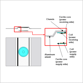
Considering corrosion resistance and strength, steel plates such as SUS steel plates are used for the casings of wireless power transfer equipment. Because of this, if the leakage magnetic flux component generated from the power supply device interlinks with the metal casing, stray loss occurs resulting in a decrease in efficiency. Therefore, when the loss component is high, it is necessary to suppress the loss by providing for example an aluminum shield.
Since in order to accurately calculate stray loss it is necessary to accurately calculate the flow of magnetic flux interlinking with steel plates or aluminum shields and the eddy current distribution caused thereby, electromagnetic field analysis using finite element methods is necessary.
In this example, an example is presented investigating by using electromagnetic field analysis whether stray loss can be suppressed using an aluminum shield.
Stray Loss Distribution

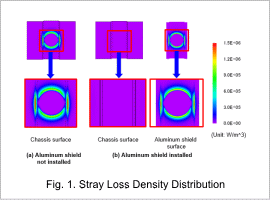
Fig. 1 shows the stray loss distributions of the chassis and aluminum shield. Regardless of the presence or absence of the aluminum shield, it can be seen that stray loss due to leakage flux is generated around the ferrite cores. After installing an aluminum shield on the surface of the chassis, it is possible to confirm that almost no loss is generated in the chassis due to this shielding with loss occurring only on the aluminum shield surface. In addition, it can be confirmed that there are places with higher stray loss density with the aluminum shield installed as compared to before the aluminum shield was installed.
Difference in Stray Loss With and Without an Aluminum Shield

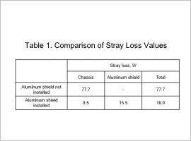
Table 1 shows stray loss values due to eddy currents. It can be confirmed that the stray loss could be reduced when an aluminum shield was installed even though the stray loss density on the surface was higher. This is because the skin thickness decreased and the volume where the loss occurred decreased since aluminum was used which has higher conductivity than the SUS material used for the chassis.


