Overview
Efficiency maps require a significant amount of calculations, and organizing results can also take a considerable amount of time. Although it is possible to estimate efficiency by calculating the torque, voltage, and current from motor voltage equations and torque equations, there exists several issues in the difficulty involved in using this method to estimate loss and account for the effects of the nonlinear magnetization characteristics of the motor iron core, as well as accurately calculating efficiency, which can also prove to be similarly challenging.
Through simulations using the finite element method, however, efficiency maps that account for the effects iron loss and nonlinear magnetization characteristics can be written with ease. Comparing motor performance in varying design proposals is also a simple process.
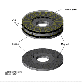
In this example, the motor performance of axial gap-type motors with changes made to the flatness ratios.
Comparison Conditions
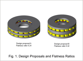
Motor volume, gap length, magnet quantity, and windings remain the same for both design proposals.
Efficiency Maps
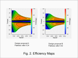
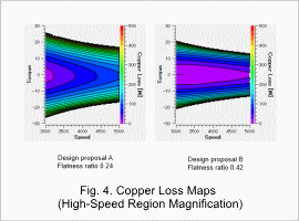
The efficiency maps for design proposals A and B are shown in Fig. 2, while the copper loss maps are shown in Fig. 4.
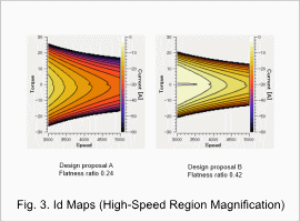
From Fig. 2, it is understood that maximum torque is large in low-speed regions for design proposal A, and design proposal B reaches high efficiency in high-speed regions. A low flatness ratio means a larger gap surface area where torque can be generated, therefore increasing maximum torque. A high flatness ratio decreases the field magnetic flux that occurs due to permanent magnets, and the load d-axis current required for weakening magnetic flux decreases. This leads to a reduction in copper loss, thus leading to high efficiency (Fig. 3, Fig. 4).
It is thereby understood that motor performance can be adjusted by making changes to the flatness ratio of axial gap-type motors.
