*Please prepare a license ID and password for the license administrator.
*It is different from the service for JMAG WEB MEMBER (free membership). Please be careful.
Overview
With advances in variable speed operation technology for induction motors, progress is being made in applications to fields where wide operating regions are required. An effective method of evaluating the characteristics of induction motors in fields like these is to create efficiency maps for the operating regions.
Simple calculations that do not account for harmonics that enable the faster creation of efficiency maps are effective for concept designs that are narrowed down from a larger number. When concept designs have then been narrowed down to a certain extent, efficiency maps can then be created which do account for harmonics, which then allows for more accurate evaluations to be run.
In this example, efficiency maps are created for a three-phase induction motor accounting for PWM carrier and slot harmonics. These are compared with efficiency maps when harmonics are not accounted for.
Circuit Diagram
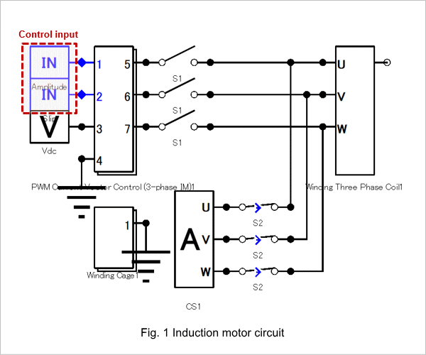
The circuit diagram of the induction motor is shown in Fig. 1. Control is accounted for by the circuit.
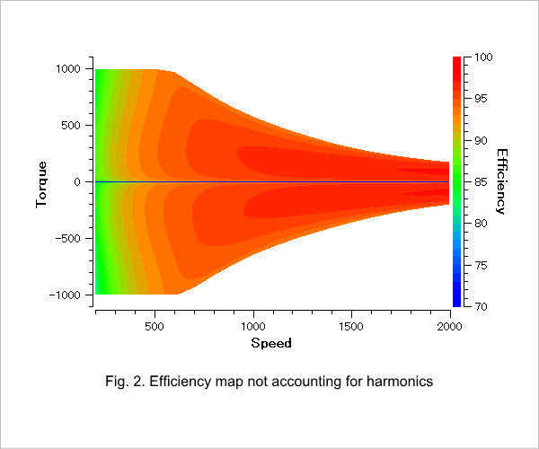
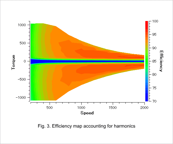
Efficiency Map, Ratio Map
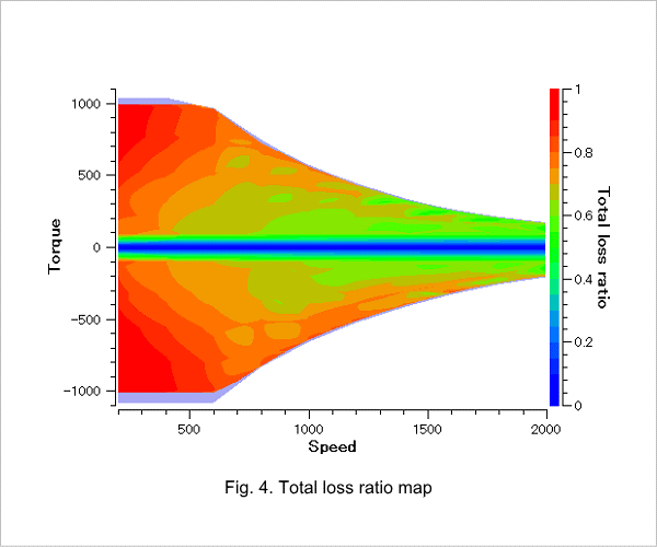
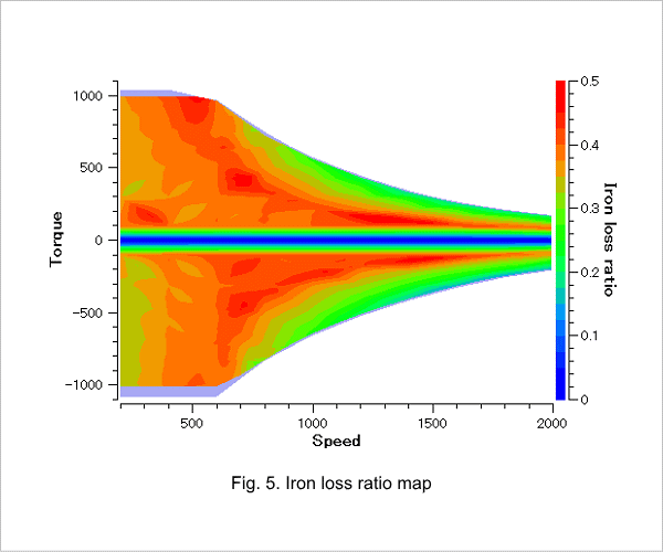
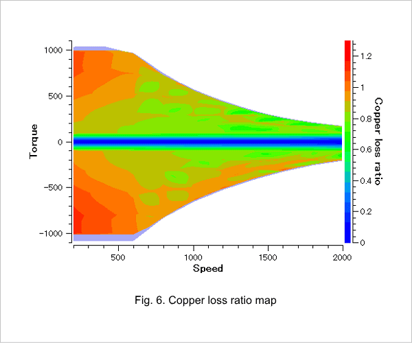
An efficiency map not accounting for harmonics is shown in Fig. 2 and an efficiency map accounting for harmonics is shown in Fig. 3. Ratio maps for the total loss, iron loss, and copper loss are shown in Fig. 4, Fig. 5, and Fig. 6 respectively when harmonics are or are not accounted for.
Efficiency at operating point 1600 rpm, 180 Nm is 96.5% when harmonics are not accounted for and 04.7% when harmonics are accounted for, showing a 1.8 point difference. A look at the high-speed region shows a large difference in loss for both iron and copper.
High-Speed Region Loss Components
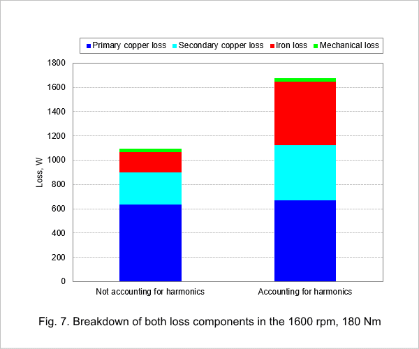
The breakdown of loss components when harmonics are or are not accounted for in the high-speed region (1600 rpm, 180 Nm) is shown in Fig. 7. When harmonics due to PWM carriers and slots are accounted for, both iron and secondary copper losses are larger than when harmonics are not accounted for because the corresponding iron and secondary copper losses are included.

