*Please prepare a license ID and password for the license administrator.
*It is different from the service for JMAG WEB MEMBER (free membership). Please be careful.
Overview
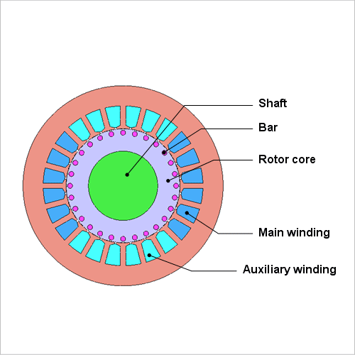
Single phase induction motors are widely used as small output motors for the drives in household electrical appliances and office machinery, like fans and washing machines, because they can use single phase AC, the typical power source for home electronics. Unlike three phase AC, however, single phase AC cannot create a rotating magnetic field by itself, meaning that it cannot start a motor. For this reason, it needs to use an alternate method to generate a rotating magnetic field to start the motor.
It is important to verify whether or not torque is generated in the intended direction and continues to rotate stably ahead of time in the design phase. In order to carry out this verification, the conditions where the rotor follows the equation of motion according to the electromagnetic force mechanism and starts up need to be analyzed correctly.
The purpose of this Application Note is to introduce an example of a single phase induction motor that uses a capacitor to set up an auxiliary winding and show its rotation speed versus time, torque versus time, and the magnetic flux density distribution and current density distribution in the bar just after the motor starts.
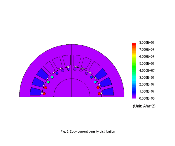
Magnetic Flux Density Distribution, Eddy Current Density Distribution
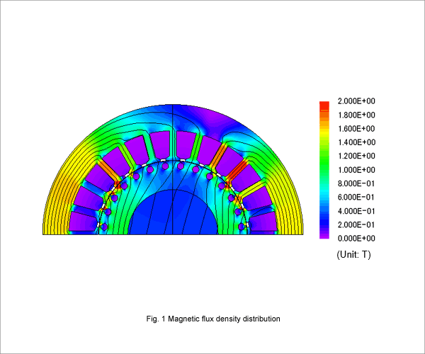
Fig. 1 shows the magnetic flux density distribution right after the motor startup, and Fig. 2 shows the eddy current density distribution of the secondary conductor bars.
The magnetic flux generated by the winding causes eddy currents in the secondary conductor bars, generating a rotating magnetic field.
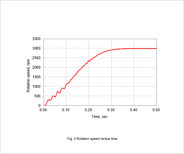
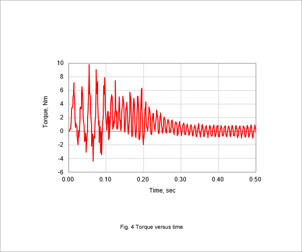
Starting Performance
Fig. 3 shows the rotation speed versus time graph, and Fig. 4 shows the torque versus time graph.
The time from motor startup until it reaches the synchronous speed is determined by the capacitance of the capacitor. The slip is very small when the motor reaches synchronous speed, so the average torque becomes zero.