*Please prepare a license ID and password for the license administrator.
*It is different from the service for JMAG WEB MEMBER (free membership). Please be careful.
Overview

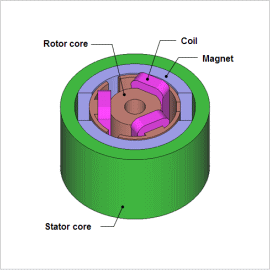
A brush motor generates torque through the electromagnetic attraction and repulsion between its rotor and stator. They do not have many parts and do not require drive circuits, so they are widely used as a power source for compact equipment. A brush motor is composed of a magnetic circuit part, which actually generates torque via electromagnetic phenomena, and the brush/commutator part, which corresponds to the drive circuit. In order to aim at improving the performance of a brush motor, it is necessary to raise the usage efficiency of the magnetic circuit in each part and expertly utilize the nonlinear material characteristics. Proper placement of the brush/commutator that correspond to the drive circuit is also vital.
In order to evaluate the usage efficiency of the magnetic circuit, torque variations, current waveforms, etc. at the design stage, it is best to first do a detailed calculation of the magnetic flux density in each part, and then perform an electromagnetic field simulation using the finite element method (FEM), which can evaluate torque with high accuracy.
This document introduces how the characteristics of the brush-type PM motor can be obtained, including torque versus current (T-I), torque versus speed (T-N), and magnetic flux density distribution.
Speed-Torque Curve/Torque-Current Curve
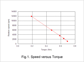
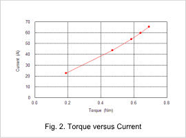
Fig. 1 shows the Speed-Torque curve, and fig. 2 shows the Torque-Current curve. From both characteristic graphs it is possible to confirm that it has obtained the characteristics of a DC motor, such as the fact that the rotation speed and current are proportional to the torque. The controllable speed range in this motor can also be seen on the Speed-Torque curve.


Magnetic Flux Distribution

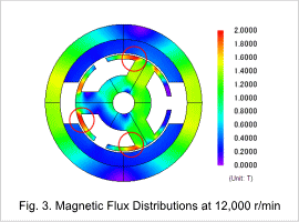
The magnetic flux density distribution at a rotation speed of 12000 r/min is shown in fig. 3. The magnetic flux density is particularly high in the regions circled in red. The magnetic flux from the rotor and the stator concentrate there. This magnetic flux produces torque. When magnetic flux leakage occurs due to magnetic saturation, the torque may be reduced.


