*Please prepare a license ID and password for the license administrator.
*It is different from the service for JMAG WEB MEMBER (free membership). Please be careful.
Overview

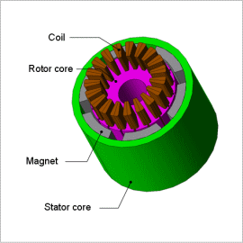
Small brush motors generally have a structure containing 2 poles and 3 slots, but there are times when a multi-pole structure is adopted in order to produce higher torque. The reason for this is because achieving a higher torque makes it possible to omit deceleration systems. Brush motors have a construction where the number of poles and number of slots are not divisible, with the objective of raising the rectification effect or limiting torque variations. In exchange for reducing torque variations, however, there is a drawback when it comes to torque output. This is why selecting the number of poles and slots have become a design theme, especially when it comes to small motors, which have a small number of slots. This makes the selection process difficult because the difference in distribution becomes large. The model for this analysis has 6 poles and 19 slots, so there are 3.16 slots per pole. They cannot be divided into decimals however, so there have to be either 3 or 4 slots for each magnetic pole. As a result, the induced voltage in each coil and the torque generated are unbalanced.
These evaluations need to be able to account for an accurate circuit geometry, and the current flowing through coil connected via a commutator needs to be handled accurately, as well. This is why an electromagnetic field analysis using the finite element method (FEM) is necessary to account for everything.
This Application Note presents an analysis to obtain the speed versus torque and torque versus current for a motor that has 2 brushes, 6 poles, and 19 slots.
Speed-Torque Curve and Torque-Current Curve
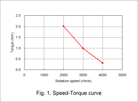
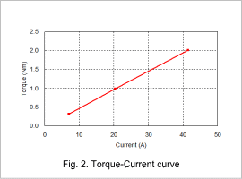
Fig. 1 shows the speed versus torque curve and fig. 2 shows the current versus torque curve.
As shown in fig. 1, the torque in the DC brush motor decreases as the rotation speed increases. This is because the current flowing in the coil is reduced by the increase of reverse electromagnetic force produced as the rotation speed increases. As shown in fig. 2, the relationship between the current and torque is mostly linear, and the torque coefficient of this brush motor is 0.05 Nm/A.


Magnetic Flux Density Distribution

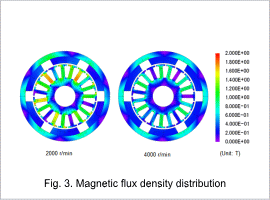
Fig. 3 shows the magnetic flux density distribution at rotation speeds of 2000 r/min and 4000 r/min.
The magnetic flux density increases at lower a lower rotation speed, as indicated in the figure. This is because the current flowing in circuit is larger, as mentioned earlier. A motor and control design that does not allow magnetic saturation to occur at low rotation speeds is desirable because the performance of the motor worsens with magnetic saturation.
The magnetic flux density increases at lower a lower rotation speed, as indicated in the figure. This is because the current flowing in circuit is larger, as mentioned earlier. A motor and control design that does not allow magnetic saturation to occur at low rotation speeds is desirable because the performance of the motor worsens with magnetic saturation.


