*Please prepare a license ID and password for the license administrator.
*It is different from the service for JMAG WEB MEMBER (free membership). Please be careful.
Overview

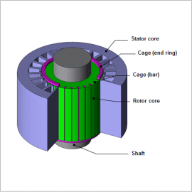
Single-phase induction motors are widely used as small output motors for the drives in household electrical appliances and office machinery, like fans and washing machines, because they can use single-phase AC, the typical power source for home electronics. Unlike three-phase AC, however, single-phase AC cannot create a rotating magnetic field by itself, meaning that it cannot start a motor. For this reason, it needs to use an alternate method to generate a rotating magnetic field to start the motor.
The induced current flowing in the secondary conductor largely affect the performance of the motor because the motor rotates by using the interaction between this current and the magnetic field of the stator coils. Strong magnetic saturation distribution is also generated near the gap, so the nonlinear characteristics of the magnetic properties have a big influence on performance, as well. At the step before the design phase, it is helpful to run an analysis and evaluation using the finite element method (FEM) to understand a single-phase induction motor’s characteristics by accounting for induced current and magnetic saturation characteristics.
This Application Note explains how to obtain the current density distribution and Speed-Torque curve created by auxiliary winding that uses a capacitor.
Current Density Distribution

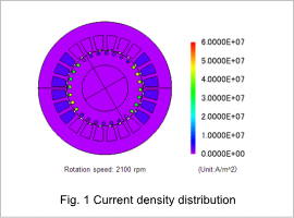
The current density distributions for maximum torques at rotation speeds of 2,100 rpm are shown in fig. 1. The difference in speed between the rotor and rotating magnetic field becomes smaller as the rotor reaches high speed. This makes the variations in the magnetic field acting on the cage grow smaller, which in turn reduces the eddy currents flowing in the bars accordingly. The eddy current distribution in the bars largely affects the torque characteristics.
Speed-Torque Curve

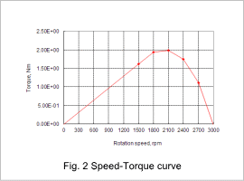
The Speed-Torque curve is shown in fig. 2. The maximum torque can also be obtained at around 2000 rpm. The rotation region that provides maximum or high torque varies depending on the electric resistance, so changing the cage materials or geometry makes it possible to study the motor characteristics that most closely meet the goals of the design.


