Overview
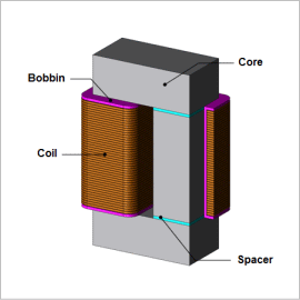
Using a finite element analysis (FEA) to confirm the distribution of iron loss density makes it possible to study a reactor’s local geometry during its design, so it is useful in providing feedback about the design itself.
This Application Note analyzes the iron loss of a reactor.
Magnetic Flux Density Distribution/Iron Loss Density Distribution
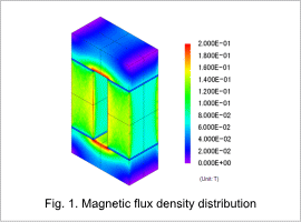
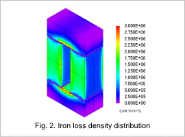
The core’s magnetic flux density distribution and iron loss density distribution are shown in figures 1 and 2, respectively. The magnetic flux concentrates on the surface because it cannot flow easily in the direction of the laminations, increasing the iron losses accordingly. The magnetic flux also tries to flow through the shortest path in the magnetic circuit, so the magnetic flux density and iron loss are large at the top and bottom of the core, which are not wrapped by the coil.
Joule Loss Density Distribution/ Hysteresis Loss Density Distribution
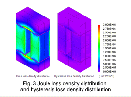
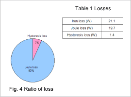
The core’s joule loss density distribution and hysteresis loss density distribution are shown in fig. 3, the ratio of losses is shown in fig. 4, and the losses are shown in table 1. As can be seen from the figures, the contribution of the joule loss toward the iron loss is large. The amount of core loss may be effectively decreased by reducing the amount of Joule losses.
