*Please prepare a license ID and password for the license administrator.
*It is different from the service for JMAG WEB MEMBER (free membership). Please be careful.
Overview
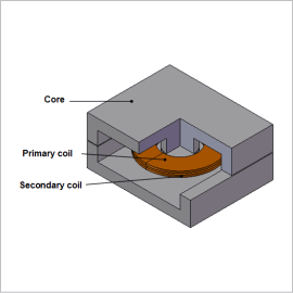
Power transformers need to be able to operate over the long term, so they are always required to control running costs from losses. Iron loss is one of the main losses in a transformer, and it can lead to temperature increases and efficiency decreases because it consumes electric power as heat in a magnetic material.
Using a finite element analysis (FEA) to display the iron loss density distribution and obtain the iron loss values in a transformer makes it possible to study the local geometry and get design feedback at the design stage.
This Application Note shows how to obtain the iron loss of a sheet coil transformer.
Magnetic Flux Density Distribution/Iron Loss Density Distribution
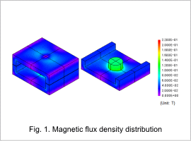
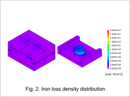
The core’s magnetic flux density distribution and iron loss density distribution are shown in figures 1 and 2, respectively. The magnetic flux density distribution and iron loss density distribution are similar, as indicated in the figures. This is because the frequency of the magnetic flux density variations is constant, so the size of the iron losses is proportional to the size of the magnetic flux density variations.
Joule Loss Density Distribution/Hysteresis Loss Density Distribution
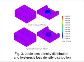
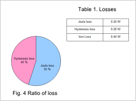
The core’s joule loss density distribution and hysteresis loss density distribution are shown in fig. 3, the ratio of losses is shown in fig. 4, and the losses are shown in table 1.
