*Please prepare a license ID and password for the license administrator.
*It is different from the service for JMAG WEB MEMBER (free membership). Please be careful.
Overview

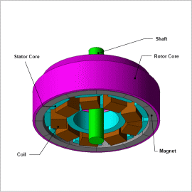
Spindle motors are often used as drive motors where limited space is an issue, as is the case with storage media like hard disks. They employ an outer rotor structure in order to obtain a large torque, but to do so they have to use a great deal of permanent magnets while remaining thin and compact. In order to reduce the number of parts used in their composition, the rotor core has functions that both bear the magnet’s flux path and transfer the generated torque, which supports the magnet, to the shaft. For this reason the rotor core is composed of materials that are easy to produce, meaning that there is a possibility that its efficiency as a magnetic circuit will decrease. As motors get smaller, they require a design that accounts for flux leakage because it begins to affect the disc in the rotor.
For this reason, spindle motors need electromagnetic field simulations that use the finite element method (FEM), which can account for detailed 3D geometry and magnetic saturation in materials, in order to carry out an accurate evaluation.
In this example, how the Speed-Torque curve, the Torque-Current curve and the magnetic flux density distribution of a spindle motor can be obtained.
Speed-Torque Curve / Torque-Current Curve
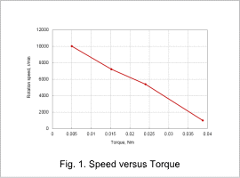
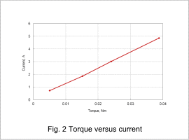
Fig. 1 shows the Speed-Torque curve, and Fig. 2 shows the Torque-Current curve.
The results show that the torque decreases as the speed increases, and increases as the current increases. From the Speed-Torque curve, it becomes apparent that the torque is almost directly inversely proportional to the rotation speed. From these results, it can be assumed that there is almost no influence from the inductance in the winding.


Magnetic Flux Density Distribution

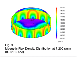
Fig. 3 shows the magnetic flux density distribution at a rotation speed of 7,200 r/min.
It can be seen that, from the spindle motor’s structure, it has magnetic flux density distribution in the rotor core’s rotation axis direction. The magnetic flux density is high in the rotor core because the rotor core is thin in the magnet’s magnetic flux direction. High magnetic flux density causes magnetic saturation, which can lead to a decrease in torque.
It can be seen that, from the spindle motor’s structure, it has magnetic flux density distribution in the rotor core’s rotation axis direction. The magnetic flux density is high in the rotor core because the rotor core is thin in the magnet’s magnetic flux direction. High magnetic flux density causes magnetic saturation, which can lead to a decrease in torque.


