*Please prepare a license ID and password for the license administrator.
*It is different from the service for JMAG WEB MEMBER (free membership). Please be careful.
Overview
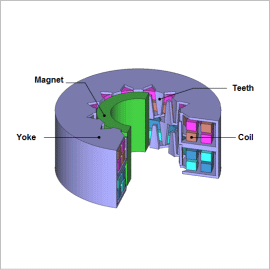
PM stepper motors are commonly used for positioning of moving parts in small devices such as printers and video equipment. In order for its drive to function with an open loop, the most important characteristics for a stepper motor are controllability and holding torque, and not the motor’s output. Therefore, the desired characteristics are detent torque, which is a non-excitation holding torque, and stiffness torque, which is an excitation holding torque.
A PM stepper motor is made up of a multi-pole magnetized rotor and offset inductors for each phase. In order to reduce their size and number of parts, claw pole inductors are made from folded steel sheet. Because of this, the flow of magnetic flux is three dimensional, so it is necessary to carry out a 3D electromagnetic field analysis using the finite element method (FEM) to proceed with an accurate preliminary study.
This Application Note describes how the stiffness torque at 0.5 A of current can be calculated for a PM stepper motor.
Stiffness Torque
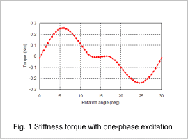
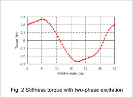
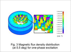
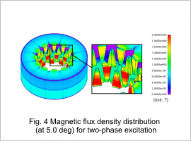
Fig. 1 shows the stiffness torque with one-phase excitation and fig. 2 shows the stiffness torque with two-phase excitation. Fig. 3 shows the magnetic flux density distribution of the yoke with one-phase excitation at a rotation angle of 5.5 deg. Fig. 4 shows the magnetic flux density distribution of the yoke with two-phase excitation at a rotation angle of 5.0 deg. A maximum torque of 0.26 Nm is obtained at 5.5 deg for one-phase excitation, and 0.27 Nm is obtained at 5.0 deg for two-phase excitation. The magnetic flux density is concentrated at the inductor regardless of the excitation.
