Effectiveness of FEA in the Development Process
Electromagnetic field finite element analysis (FEA) has been rapidly expanding as a tool used in the development process over the last 15 years. The application of FEA varies based on the needs of each development process, but why has FEA expanded so rapidly as a tool for development? In addition, what are the advantages of using FEA in the development process?
Impact of FEA on the Design Process will introduce how FEA has effected the development process from multiple perspectives over the next year.
Before FEA
FEA is well known as an analysis method using a computation solver. In recent years, the utilization of specialized computation solvers for FEA in the development process is not unusual. Furthermore, large scale analyses exceeding a million elements or analyses that have multiple cases are being used more frequently. However, this was not the case a quarter of a century ago due to the limitations and cost of the computation solver performance.
Therefore, how did FEA enter into the development process as a design tool at that time?
The simple answer is years of intuition and experience. However, the magnetic circuit method has been used systematically as the primary method to analyze the magnetic characteristics of electromechanical machines. The magnetic circuit method is a universal analysis method that is used widely even today, but, it was the only analysis method available at the time because the computation solvers were not as sophisticated as they are today.
The magnetic circuit method is a method to estimate the magnetic flux produced in the magnetic pathways of the magnetic circuit by replacing the core, coils, and magnets making up a machine with a magnetic circuit composed of the source of magnetomotive force and magnetic resistance. An example of a magnetic circuit overlayed on a motor is indicated in Fig. 1. This method can be calculated by hand without a computation solver because large scale calculation is not required for a simple magnetic circuit. The electromagnetic attractive force between the stator and mover obtained using the simple magnetic circuit method for the solenoid value shown in Fig. 2 is indicated in Fig. 3. In Fig. 3, the calculation results using FEA are compared to the simple magnetic circuit method to show the similarity of the results regardless of which method is used.
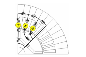 Fig. 1. Magnetic circuit of a motor
There are also software based on the magnetic circuit method. Results can be obtained instantly because an analysis can be performed using very few calculation resources.
Therefore, the magnetic circuit method was widely used in the design process before FEA become a standard tool (before FEA).
Then why has analysis using FEA become necessary and widely adopted in the development process?
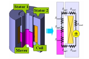 Fig. 2. Model of a solenoid valve using the magnetic circuit method
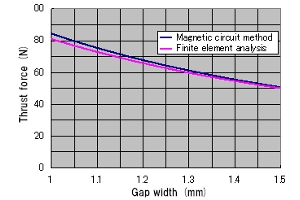 Fig. 3. Attractive force characteristics obtained using the magnetic circuit method in Fig. 2
Why is FEA being widely adopted?
The magnetic circuit method is a convenient method that can obtain results simply and easily, but a more authentic magnetic circuit is required to obtain more accurate results. The primary magnetic pathways the magnetic flux flows need to be predicted and the magnetic resistance of the magnetic circuit needs to be evaluate in advance to define the magnetic circuit. This requires the intuition and experience of designers.
The magnetic circuit is also strongly dependent on the geometry and material properties. The magnetic circuit that needs to be taken into account becomes complex as the geometry becomes complicated. A point sequence of each operating point for the physical values and magnetic resistance also becomes necessary to grasp the nonlinear properties of materials.
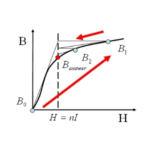
The characteristics of the attractive force indicated in Fig. 3 for a wider operating region are indicated in Fig. 4. The error in the magnetic properties is expressed as the error of attractive force because the magnetic saturation is more severe as the gap between the mover and stator becomes thinner (linear properties are assumed in the magnetic circuit method). The geometrical dependency of the attractive force is more prominent as the gap becomes thinner because the magnetic resistance varies largely with the geometry. This means the application of the magnetic circuit method becomes more difficult with the complexity of the geometry for an analysis target that is dependent on nonlinear characteristics.
The geometry often needs to be determined while comprehensively investigating the magnetic saturation and loss distribution of the primary magnetic circuit to achieve the maximum performance of machines, such as motors, during the design process. However, the magnetic circuit method cannot account for distributions such as the magnetic flux density distribution and loss density of a machine by simply replacing and calculating an equivalent circuit for an analysis target.
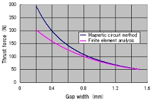 Fig. 4. Attractive force characteristics when expanding the operating range of Fig. 3
FEA is suitable for these kinds of evaluations. The magnetic flux density distribution inside a motor can be comprehensively evaluated using FEA as indicated in Fig. 5. In addition, physical phenomena reflected in geometry, such as the torque ripple, can be examined in detail easily.
FEA performs analyses by modeling the geometry as closely as possible to the actual machine and setting accurate values for the material properties without relying on the intuition and experience of the designer. Therefore, highly accurate results can be obtained by anyone even if they are not an expert in design by following the correct modeling procedures.
FEA can even examine the magnetic saturation and eddy current distribution inside of machines that cannot be directly evaluated using measurements. More information can be acquired using FEA than can even be obtained through experimentation.
The rapidly increasing performance of computation solvers and the technical advancements of analysis methods in recent years are drastically expanding the prevalence of FEA. This has resulted in the rapid application of FEA in the development process.
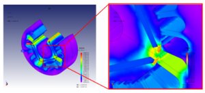 Fig. 5. Magnetic flux density distribution inside a motor
This issue has provided a broad overview for the prevalence and background of FEA in the design process. The next issue will describe the technical background that has made comprehensive and highly accurate analysis possible using FEA.
[JMAG Newsletter Spring, 2011]