Effectiveness of FEA in the Development Process
This report introduces FEA's characteristics, which include an excellent analytical ability, in order to examine both the advantages they bring to the development process and the utilization methods for applying them. In this, the final issue, I will introduce applications to failure modes, which is a new way of using FEA.
Using FEA allows us to obtain information that is not available through an actual device test. It can give us substantially greater insight into the device's performance.
1. Overview
When a company releases a new electrical device, it must first confirm the conditions under which the device will operate correctly. The kind of safety demanded ensures that a product will operate without any accidents under loads that fall within, and even exceed, its guidelines. In order to secure safety, one needs to assume loads that surpass the guideline values ahead of time and have some leeway at the design stage. From there, it is necessary to put together a plan to predict and prevent accidents by using a failure mode simulation based on a prototype verification. In reality, however, it is not rare for situations to occur in which products are recalled after release and undergo further verification because of unexpected accidents. Even if one uses a real machine test prior to release as a failure mode evaluation, when an accident happens it is often said that it occurred because the real machine test was insufficient. It is important to remember, however, that it is difficult from a cost perspective to prepare real machine tests that ensure completeness, and even if it were possible to prepare a complete testing environment, there is a great deal of danger involved with the machine test itself.
If it were possible to simulate a failure mode evaluation, all of the events would occur in the virtual space of a computing machine, meaning that there would be no danger involved. With a simulation, it is easy to test setting values that would be difficult to achieve in reality, so it is possible to reduce the evaluation items from an actual machine test and restrict them to a minimum level. Failure mode evaluations that use simulations are as important as, if not more important than, advance evaluations during the design process.
2. The technology required for simulating failure modes
What exactly are the necessary requirements for a simulation when performing a failure mode simulation? When examining actual failure modes, it becomes apparent that they are typically categorized as thermal or structural phenomena, such as heat generation and vibration/degradation.
However, these only raise the issue of phenomena that can be seen visually, while the physics that occur in the interior is more complicated and varied because they have interactive relationships. Among electrical products, copper loss and iron loss tend to be the causes of heat generation phenomena.
On the other hand, vibration and degradation phenomena occur when the electromagnetic force causes an excitation force. These phenomena, however, are not merely thermal or structural, but are instead composite phenomena related to the electromagnetic force. This is why one has to be able to model various and complicated physical phenomena in a failure mode evaluation and simulate the actual circumstances. Simulation technology with a high degree of detail is necessary to apply the information required for a phenomenon simulation in a model.
Failure mode simulation is also an important indicator for determining the advisability of a product release, so when a problem occurs during an evaluation, one needs to be able to diagnose the cause easily and implement any improvement strategies in the design right away. This is why it is necessary to possess simulation technology that has high analytical ability and can analyze outcomes instead of merely obtaining a highly accurate, detailed analysis result.
We highly recommend FEA as a simulation technology that fulfills these needs. I will examine the reasons that FEA is the simulation technology that is best suited for failure mode simulations in the following sections.
3. Why FEA is effective in failure mode simulations
With FEA, it is possible to match the material properties and conditions necessary for an analysis with actual conditions, and to apply the contents that have been set up in the analysis correctly. For example, you can input the points to define the BH curve of a material. Defining this curve means that the simulation will incorporate the nonlinear properties of the material, and this should increase the accuracy of the simulation. The higher the accuracy of the point sequence that has been entered, the closer the result is to the actual phenomenon. FEA also allows you to simulate complex interactions as described in the previous section. For instance, you can simulate the temperature of a device by first simulating the electromagnetic losses and then apply those losses to a thermal analysis model, because the device's temperature is a function of an electromagnetic simulation driving a thermal simulation. You can also couple these two simulations and run them together so that the changes in one directly affect the other. In other words, the losses drive a temperature change which then alters the material properties, and the new material properties are then reflected in the electromagnetic loss model.
By using FEA, you can gain insight into phenomena that are either difficult or impossible to measure directly. For example, you can use a FEA to determine the magnetic flux density of a device and confirm whether the magnetic design is correct, or if there is unintended saturation. Even complex interactions such electromagnetic force and vibration can be investigated by isolating the phenomena through a coupled FEA. In this case the excitation force distribution and stresses are driven by electromagnetic forces. These forces also change the material properties, which in turn effect the amount of electromagnetic force generated.
Through FEA you can examine the problem from multiple viewpoints and create output that will help visualize the phenomena under examination. You can also predict unintended problems and determine their solution. Though coupled analysis we can thoroughly examine how and why a device fails.
These are all reasons why FEA is a simulation technology that fulfills the requirements demanded for failure mode simulations.
4. FEA's advantages as seen through case examples
The following two examples examine how FEA can be used in specific failure mode analyses.
4.1 Demagnetization evaluation of the magnet inside of a motor during drive
A common fault in a motor during drive is a breakdown of the transformer insulation in the inverter, which produces a short circuit (fig. 1). This short circuit generates a massive current, which produces a reverse magnetic field and generates heat, creating demagnetization in the motor's permanent magnet (fig. 2). The resulting demagnetization causes the motor's characteristics to change, making it possible to assume that the entire system, including the motor, will be affected. A failure mode analysis needs to confirm the influence from demagnetization on the motor's characteristics and build countermeasures into the design[1].
Using FEA to do the analysis makes it possible to perform a failure mode simulation that uses a coupled analysis with a control circuit that includes an inverter, like the one above. With this simulation, it is possible to predict the temporal changes of the demagnetization phenomena that occur after an accident. Excellent analytical ability, one of FEA's characteristics, allows you to get an understanding of the magnet's local demagnetization situation (fig. 3). By forecasting which part of the magnet is influenced by demagnetization the most, you can study alignments and materials that make it difficult for demagnetization to occur.
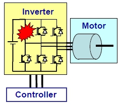 Fig. 1 Damage in the transformer that composes an inverter
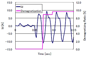 Fig. 2 Increase in D-axis current and development of demagnetization caused by a short circuit
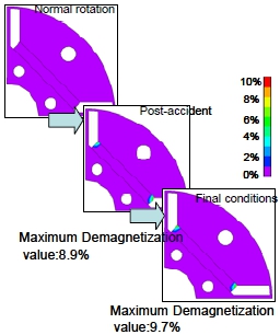 Fig. 3 Temporal changes in the demagnetization distribution of the magnet in a rotor
4.2 Stray losses and heat generation in a large transformer
The transformers used in power plants and substations generate a great deal of heat in the surrounding chassis. This heating occurs because of flux leakage from the transformers themselves and because the high current flowing in the bus bars results in stray loss. Even if the temperature level is below the upper limit of the transformer, it may still result in someone getting burned if they touch the chassis. This is why a thermal analysis of the transformer must also include temperature levels in the chassis, and not just the transformer itself. It is especially important to estimate the maximum achieving temperature that is generated locally, meaning that an accurate evaluation of the temperature distribution is necessary. Stray loss, which generates heat, also occurs in places not originally assumed to be magnetic circuits. For this reason, it is difficult to use just a magnetic circuit or empirical values when estimating loss distribution (fig. 4).
Estimating the temperature distribution of these heat sources becomes an even more difficult task if the stray losses do not have good distribution accuracy. It is possible to use actual machine tests to perform verification, but with a large-scale transformer, the facilities, which include the transformer itself, are extremely expensive to construct. For this reason, it is hard to think that advance verification using a prototype would be realistic from a cost perspective. This is why advance forecasts using FEA are indispensible[2].
This analysis handles composite phenomena made up of an electromagnetic phenomenon and a thermal phenomenon, so a magnetic field-thermal coupled analysis is necessary. First, the magnetic field analysis is used to obtain three losses: Copper loss in the coil, iron loss in the core, and stray loss in the chassis. Next, these losses are used as heat sources to carry out a temperature distribution analysis and estimate both the final temperature distribution and maximum achievement temperature in each of the parts (fig. 5 and fig. 6). The loss distribution and temperature distribution obtained from this analysis are then used to study the arrangements of the coil, core, and chassis, which contain the local heat generation. Using FEA and doing a simulation in this way allows you to objectively investigate the physical phenomena that occur in the total facilities, which include the transformer, and use them in a design.
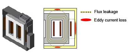 Fig. 4 Geometry of a large-scale transformer, including the chassis(left)
and an image of stray loss generation caused by flux leakage(right)
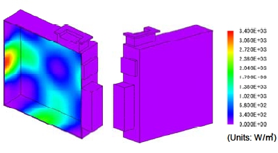 Fig. 5 Stray loss distribution in the chassis
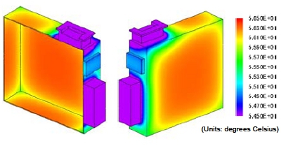 Fig. 6 Temperature distribution in the final state of the chassis
5. In Conclusion
In this issue, I introduced FEA as a simulation technology that can be used to predict failure modes in a device.
In addition to having excellent capabilities when simulating physical phenomena, FEA makes it possible to carry out a wide range of failure mode evaluations and to analyze their causes in great detail. For this reason, one can think of FEA as a simulation technology that provides additional insight beyond actual machine testing.
I hope that everyone will use FEA to give a new added value to their development process.
(Takayuki Nishio)
[1] This case example from a JMAG user comes from John Deere's presentation documents at the JMAG Users Conference 2011: "Electric Drives for Off-Road Mobile Equipment."
[2] This case example from a JMAG user comes from Japan AE Power Systems Corporation's presentation documents at the JMAG Users Conference 2010: "Study of Local Heating on by IPB Connection Box and Around Metallic Parts of Large Power Transformer by 3-D Magnetic Field Analysis."
The two presentation documents mentioned above are listed on the Website for JMAG users. We will send a CD version of the Users Conference proceedings, so please contact the Users Conference Secretariat if you would like to receive a copy.
[JMAG Newsletter Winter, 2011]