FEA Expansion to the Product Development Process
Among those reading this magazine there are most likely some who think that, because they began development in an era when there was no FEA and their design process is already set in stone, there is no point in starting to develop with FEA at this late stage. There are also probably quite a few who are interested in FEA, but cannot picture how they would actually be able to extend it to the design process.
In this issue, by taking another look at the product development process up to the present, I would like to exhibit the fact that there are places in which FEA is actually able to play a large role in various development process situations, including design.
Being Able to Verify the Product Development Process
There is an image of FEA simulation as being an advance evaluation for the product design stage. However, it is a simulation technique that has a wide range of application and can be used in verifying and evaluating every stage of the product design process.
Here I will break up the product development process into three parts: "Development Process," "Production Process," and "Operation Process," and I will apply FEA to each of these. I would also like to show that FEA is a technique that does not just raise the efficiency of each process, but also makes it possible to build in quality as a long term viewpoint, from the initial steps of development to design, production, and operation.
I will focus on motors as concrete product examples.
Usage in the Design Process
Fig. 1 displays a typical, traditional motor design process that does not use FEA.
Generally, in a typical electrical equipment design, it is normal to proceed by fulfilling the required specifications while getting a balance between magnetic loading and electrical loading. However, in cases where there is no leeway in the design or when it is necessary to look for the optimal balance between both sides, there often arises a competition between thickening the iron core and avoiding magnetic saturation or getting coil space and increasing the number of turns. In studies using only empirical value and self manufacturing tools, there is a tendency for the level of reliability from a precision standpoint to be insufficient, especially in designs like those above that reflect even slight changes in geometry while accounting for magnetic saturation.
At this point I would like to address typical problems that arise in the design process.
- Magnetic circuit confirmation: In motors with strong salient properties there are cases which are difficult to evaluate without FEA.
- Magnetic permeance: Permeance evaluations during operation can be complicated because one must take the rotation motion, and not just the excitation current, into account.
- Induced voltage during operation: In motors with strong salient properties, quite a few harmonic components aside from the basic frequencies appear, so quantitative evaluations can be difficult.
- Loss evaluations: It is possible to estimate copper loss to a certain extent, but the distributions for iron loss and eddy current loss can be complex, so evaluations can be difficult.
Limiting usage to empirical value and self manufacturing tools that are based on past data also produces the demerit of only being able to obtain ideas and outcomes in initial studies during design that are limited to the range permitted by such value and tools.
For example, the influence from demagnetization caused by eddy currents in magnets can be understood after going through an evaluation that takes such influences into account. Assuming that geometry and magnetic properties are the only things that can be accounted for with empirical value and tools, no matter how many times you replace this data and study it, it is impossible to arrive at a correct evaluation that takes eddy currents into account.
By using FEA for these problems, one can evaluate quantitatively and objectively.
For magnetic circuit confirmation, it is the most basic usage method for FEA, but seeing the flow of magnetic flux line density contour plots and flows of magnetic flux lines means that one is visualizing the magnetic circuit itself and confirming it. (Fig. 2) By also seeing the state of leakage of the magnetic flux, it becomes possible to confirm whether an unanticipated magnetic circuit was configured during the initial design.
For the magnetic permeance during operation, it is possible to follow chronologically to see whether the operating point for each part of the magnet is operating within the anticipated range. In places where the permeance degradation stands out, the user can obtain feedback telling him to reconsider the flux barrier geometry.
With motors that have strong salient properties that are found in implantable magnetic motors, there is a tendency for harmonic components to get on the induced voltage waveform, but waveform analysis using FFT can carry out analysis that takes this into account, in addition to being able to find out the frequency components that become problems. The loss that induces these harmonic components is also a problem, but it is possible to put it together with the induced voltage waveform and evaluate them both at once. It is also possible to use these results to divide the magnet in order to reduce eddy currents (Fig. 3), as well as to study the grade of the electromagnetic steel band.
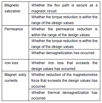
By adding the necessary corrections after the initial design problems are brought to light from the FEA analysis results, as shown in Table 1, it becomes possible to proceed to the next improved design proposal with only desktop simulations and without carrying out test production of an actual machine.
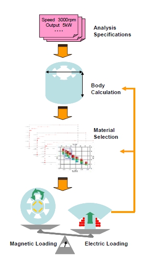 Fig. 1 An example of the traditional motor design process
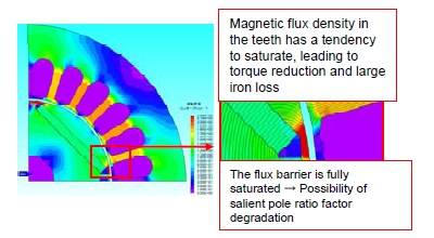 Fig. 2 Magnetic flux density distribution for a motor in an initial study
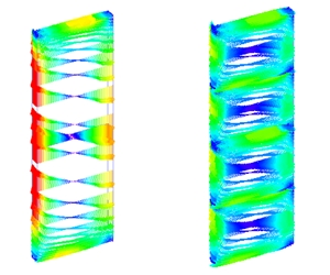 Fig. 3 Eddy current distribution of a motor magnet portion in an initial study
(Left: an undivided magnet) and post-study eddy current distribution
(Right: a magnet with 4 divisions)( Permanent magnet eddy current analysis of a JAC022 IPM motor )
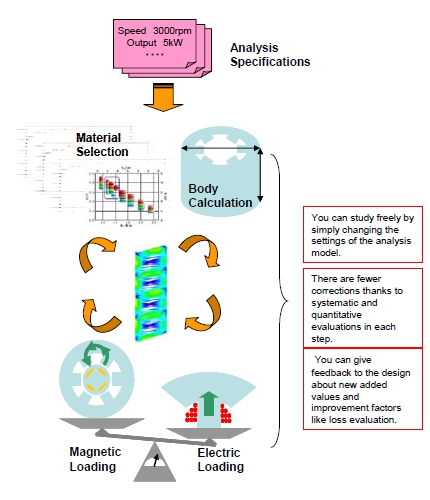 Fig. 4 Compression of the flow in Fig. 1 through FEM introduction, inclusion of added value
Table 1 Initial study case example
Usage in the Production Process
In the production phase, deviation from the cataloged value of the material properties due to processing treatment during production can become a problem. In particular, due to degradation from processing, there are times when the expected output characteristics cannot be obtained.
Traditionally people would be alright if they made a design that had a degree of leeway against degradation based on rule of thumb, but recently there has been an energy situation which has seen a trend toward hybrid cars and electric vehicles, leading to an even greater demand for high efficiency. In order to make high efficiency motors a reality, it will be necessary to cut down on this excess amount of leeway by quantitatively figuring out how much is needed.
Below I have presented the typical causes of degradation during production:
- Perforation by punching: This multiplies degradation of magnetic properties and iron loss.
- Crimping or indentation: This multiplies degradation of magnetic properties and both iron loss and eddy current loss.
- Cutting /surface fabrication: This multiplies eddy current loss.
With FEA it is possible to quantitatively compare differences in output characteristics that are found in the cataloged value by using analysis that accounts for the material property degradation associated with processing treatment. For an analysis, the magnetic properties that account for degradation need to be prepared ahead of time, but this is handled by preparing a test piece made from the same material as the product and then measuring the magnetic properties in a state of having been through a processing treatment that is equivalent to real production. Fig. 6 shows data comparing the stress dependencies of magnetic properties. Technically this is different from degradation caused by processing strain, but it is possible to confirm obvious magnetic property degradation as a function of the degree of stress.
Degradation due to processing does not only worsen magnetic properties, but also leads to an increase in iron loss. (Fig. 7)
Due to treatments like punching and crimping, the occurrence of eddy currents from upward bending in the insulation of laminated steel sheets is a problem that cannot be ignored.
By measuring the places that underwent processing treatment through microscopic observation and modeling them as a conductor that pierces through the lamination, it is possible to evaluate the iron loss. Fig. 8 shows an example that models eddy currents conducting through the lamination.
By using FEA in this way and combining it with the production process, it becomes possible to quantitatively verify and analyze the influence that deviation from the cataloged values exerts on the output characteristics.
By analyzing the amount that it contributes to the degradation and verification of each process, it becomes possible to study both estimates of the amount of leeway during the design stage and improvements in operations that make large contributions.
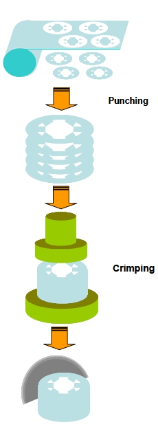 Fig. 5 An example of the production process flow
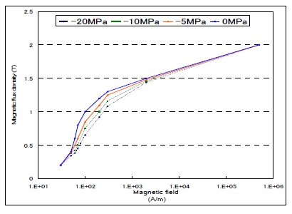 Fig. 6 A comparison graph of the magnetic properties before and after processing.
Degradation stands out in the region where saturation increases
 Fig. 7 Iron loss density distribution that accounts for production degradation.
The loss increase from punching in the tips of the tooth parts is remarkable.
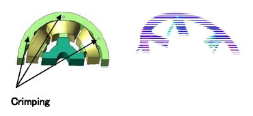 Fig. 8 An image of eddy currents between laminations caused by punching or crimping
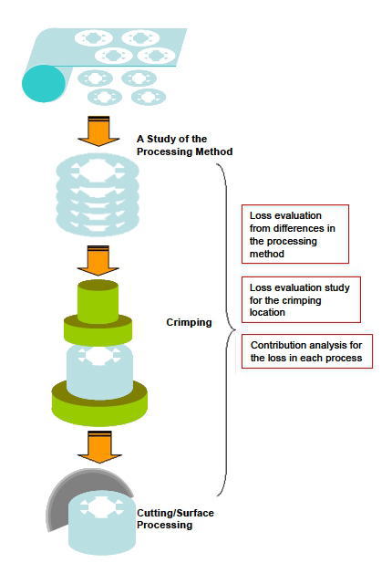 Fig. 9 A process flow, including improvements from the flow in Fig. 5
Usage in the Operation Process
Harmonic loss, vibration, and noise while the motor is running are all problems that occur in the operation stage.
Even if there are no problems in the body of the product itself, it is not rare for problems to occur after it has been mounted. Generally, when a problem occurs at the operation stage it takes quite a few man-hours to fix, so they need to be avoided as much as possible. This is why verification in advance through simulation is indispensible.
Below are concrete causes and phenomena that occur during operation. (Fig. 10)
- Magnetic coupling with the surrounding parts: Leakage reactance, stray loss
- Control waveform harmonies: Harmony iron loss, magnet eddy current loss
- Electromagnetic excitation force and machine resonance: Vibration, noise
The number of cases in which, due to miniaturization and density growth, motors have to be restricted to a limited space has started to increase. Because of this, a part of the magnetic flux that should pass through the main circuit magnetically couples with the surrounding parts such as the case, causing leakage reactance and stray loss. The impedance and loss initiated by the leakage flux depend strongly on the environment in which the motor is placed, so it becomes a case that is extremely difficult to anticipate at the design stage. For example, a reluctance motor uses inductance that changes into a rotation direction and generates torque. This is when the magnetic flux, which is generated in the axial direction, separates from the core, which is the main circuit, and becomes a cause of leakage reactance and stray loss. (Fig. 11)
Even complicated problems like this can be quantitatively evaluated with FEA. With a leakage flux problem, by modeling the surrounding conductors, including the cases, it is possible to confirm the entire magnetic circuit. At the same time with regard to stray loss as well, by looking at the distribution and not just the value it is possible to confirm the correlation with the magnetic circuit. It becomes possible to evaluate this result and the embedded environment, including the motor, with a simulation.
When the motor is activated, the PWM control method is widely used. The characteristic of this method is its high energy efficiency, but it uses a square wave that is controlled by an on/off switch, so time harmonic components appear. These time harmonic components induce harmonic iron loss and magnet eddy current loss in the core and magnet. In general time harmonic components have a high frequency compared to space harmonic components like slot harmonics and they produce a complicated distribution, so quantitative evaluations are not easy.
With FEA, a quantitative evaluation becomes possible through a coupled analysis with the control simulator by entering the current waveform, including time harmonic components dependent on the PWM controls. (Fig. 12)
Another problem when the motor is running that is just as important as loss is vibration and noise. These are phenomenon that relate directly to the five senses, so they are brought up as problems for when the motor is running. The main cause behind the phenomena of motor noise and vibration is electromagnetic excitation force. It is thought that the vibrations and noise that can actually be felt are often transferred from resonance with the motor's eigenvalue, which includes the surrounding environment as well.
In FEA through electromagnetic field analysis, by calculating the electromagnetic forces generated in the stator and carrying out vibrational and acoustic analysis with this as the excitation force, it becomes possible to evaluate the electromagnetic vibration and noise. Through analysis, one can find out how to control vibration and noise as well as make countermeasures to take out frequencies in the range of hearing that become problems, instead of simply evaluating the sound pressure and frequency of vibration that occurs. (Fig. 13, 14)
It is often necessay to evaluate the environment that the motor is embedded in when it comes to problems in the operation stage, so evaluations have to include the surrounding environment and not just the motor itself. Because of this, there are many necessary targets for simultaneous evaluations, and until now the only method was evaluation via testing of a real machine.
FEA (JMAG) is making evaluations and improvements during operation through desktop simulation possible by supporting a switch to large scale analysis and coupling with other simulations such as control simulations.
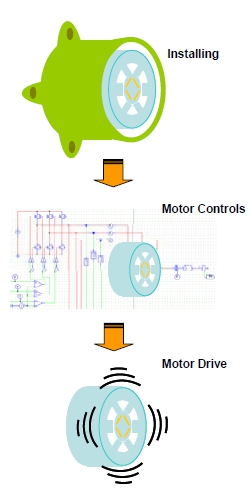 Fig. 10 An example of the flow in the operation process
Motor incorporation, drive, vibration, and noise
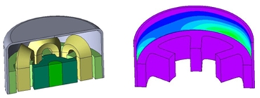 Fig. 11 Stray load loss distribution in an SRM
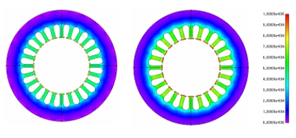
Fig. 12 Stator harmonic iron loss distribution during PWM control (Left side)
The right side, whose units are W/m^3 , is iron loss distribution in a sine
wave drive for the purpose of comparison
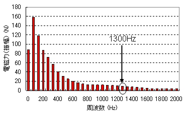 Fig. 13 Electromagnetic vibration frequency distribution
( Vibrational analysis of a JAC138 SR motor )
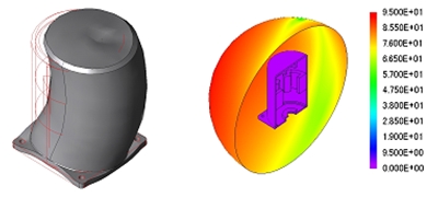 Fig. 14 A contour plot of the eigenvalues and electromagnetic vibration
The units for the image on the right are dB
( Vibrational analysis of a JAC138 SR motor )
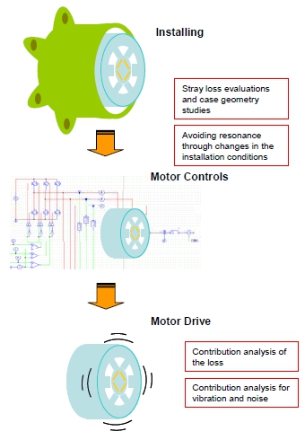 Fig. 15 The flow after improvements from Fig. 11 have been added (A comparison with Fig. 10)
In Conclusion
In this issue we have looked at products from the viewpoint of their development processes in terms of design, production, and operation. I introduced proposals for simulations that apply FEA mainly to both electromagnetic field analysis and problems initiated by electromagnetic phenomena in each phase.
Using FEA technology, which keeps the product development process in mind, makes it possible to achieve simultaneous building-in of product quality, in addition to shortening development lead time thanks to doing away with test production.
The contents of this presentation are no more than a small part of FEA's total usage method. There are also ways of using FEA that broaden one's viewpoint from product development and look at the entire life cycle of the product. FEA is also effective for verification in the unfortunate event of an accident or defect, and recently, from a reliability engineering standpoint, they have started using simulations, including FEA, in accident analysis. I would like to introduce this in written format at a later time.
As an author, it would be an honor if this issue provided the opportunity for you to undertake the task of improving the current design process.
[JMAG Newsletter Fall, 2011]]