Overview
Temperature rise in each part has become a major issue due to higher motor output density. If designers only focus on the magnetic design, the motor design will not satisfy the thermal design requirements, which could entail significant rework. That is why taking into account for the cooling system and rest of the thermal design is essential during the magnetic design stage.
Industrial motors often employ a self-ventilation system that circulates air using a fan mounted to the motor shaft. JMAG can reproduce the forced air cooling through ducts and other parts to predict the temperature changes in each part.
This case study simulates a forced air cooling system inside an induction machine using two different types of fans. The results illustrated how different airflow rates of the fans affect the saturation temperatures in each part.
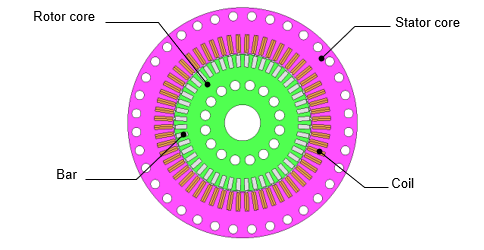
Fig 1. Induction Motor Model
This case study analyzes the forced air cooling of an induction motor using two different fans. The air from each fan flows from the stator and rotor core ducts through the gap before exiting on the other side of the motor.
You need to sign in as a Regular JMAG Software User (paid user) or JMAG WEB MEMBER (free membership).
By registering as a JMAG WEB MEMBER, you can browse technical materials and other member-only contents for free.
If you are not registered, click the “Create an Account” button.
Create an Account Sign in