Motor Design with JMAG-Express
Handy features are constantly added in our motor design tool, JMAG-Express. This article will use three-phase induction motors as an example and introduce case studies of design. We hope you will make use of JMAG-Express in improving efficiency in your design work.
What is JMAG-Express?
JMAG-Express is a motor design tool that covers examination from concept design to basic design. It also packs 2 modes: quick mode that calculates basic properties in a second and a power mode that evaluates distribution amount of magnetic flux density or loss density, time series result of cogging torque and induction voltage. Flow of motor design that makes full use of JMAG-Express (Fig.1). At the concept design stage, use quick mode for deciding on the rough layout of the motor, then use the power mode for the basic design stage and JMAG-Designer for completing the detailed design stage. This article will explain using JMAG-Express quick mode and JMAG-Express power mode.
 Fig. 1 Design Flow using JMAG-Express
Induction Motor Design with Quick Mode
I will introduce an example of three-phase induction motor design using JMAG-Express. The geometry and desired specification of the initial design proposal are shown below (Fig.2, Table 1). I will introduce an evaluation to fulfill an output of 0.5 (kW) at rated speed.
 Fig. 2 Geometry of initial design proposal
| Number of poles | 4 |
| Frequency | 50 (Hz) |
| Rated output | 0.5 (kW) |
| Rated speed | 1425 (RPM) |
| Peak Current | 50 (A) |
Characteristics evaluation of intial design proposal
Create a motor geometry using quick mode. Freely selecting and modifying combinations of rotors and stators from the template is easy in quick mode (Fig.3). Desired geometries are easily created just by modifying the dimension parameters. For this case, we have selected a rectangular model for the rotor and a constant angle of gear tip model for the stator, and by changing the dimension parameter, we were able to create a model close to the geometry of the initial design proposal (Fig.4). Results based on the specifications of the initial design proposal such as the material and winding are displayed (Fig. 5). It can be confirmed that the requirements has not been met as the rated speed has only achieved approximately 0.5 (kW).
 Fig. 3 Selecting geometry type
 Fig. 4 Intial design proposal created in JMAG-Express
 Fig. 5 Characteristics results calculated in quick mode
Performance optimization with changes in bar depth
We have evaluated whether or not motor performances can be improved by changing the bar depth of the rotor. Since the quick mode is equipped with a parametric analysis function, we used the function in deciding the depth of the ideal rotor. By selecting the variable you wish to change from the JMAG-Express data sheet, a dialog to set the parametric range will appear (Fig.6). Specify the range and the number of divisions and the parametric analysis will run when you click on the evaluation button. Once the parametric analysis is over, all case results will be displayed in one graph and easy comparison is possible (Fig, 7). Showing / hiding the graph can also be switched in the checkbox so it is easy to narrow down for examination.We will show the calculation results and bar geometry of a case where we have set the depth to 5mm like in the initial design proposal and another with 10mm (Fig.8, Fig.9).The bar depth is set at 10 mm where it is most efficient and the output meets the requirement. By changing it to 10mm, it can be confirmed that the secondary resistance decreases and the number of rotations at maximum torque has increased. Also, the output has also fulfilled the rated output of 0.5 (kW). Increasing the depth of the bar changes the cost and the mechanical strength, so confirmation in such point of view is required separately.
 Fig. 6 Parametric range settings screen
 Fig. 7 Parametric analysis results (bar depth 5mm-12mm)
 Fig. 8 Parametric analysis results (bar depth 5mm - 10mm)
 Fig. 9 Bar geometry of rotor (top: 5mm deep, bottom: 10mm deep)
Characteristics optimization with change in winding
By making effective use of the coil space, I have evaluated whether or not the characteristics can be further improved. Regularly, coil space and lamination factor must be calculated from dimensions and wire diameter on your own. However, with quick mode, lamination factor is automatically calculated from wire diameter and insulation information (Fig.10). Resistance, which changes depending on the winding type such as the coil pitch and number of layers, is also calculated automatically.
To keep the lamination factor below 40%, change the wire diameter and turns to find the ideal combination. Calculation can be done repeatedly as calculation time takes only a second. This time, there is some room left for lamination factor, so we have increased the winding from 48 to 50 turns, wire diameter from 1.1mm to 1.2mm (Fig.11). Increasing the number of turns will increase the total resistance, but by making the wire diameter larger, the resistance per unit length and total resistance has decreased, we have been able to consequently increase the efficiency. The output rises a little with the increase in turns but the rated speed hardly changes.
 Fig. 10 Winding setting screen
 Fig. 11 Calculation results after winding evaluation
Detailed Evaluation with Power Mode
After obtaining the results in quick mode, proceed with the detailed evaluations in JMAG-Express power mode. In quick mode, we performed evaluations with the averaged value of torques and such, but in power mode, you will not only be able to evaluate the distribution of magnetic flux density and the time series result of torques and such, but characteristic evaluations accounting for transient phenomena is now also possible. Create a final design proposal using power mode.
Characteristics confirmation at line start
Let's assume this induction motor starts with the most simple line start just by directly connecting to the power supply. Compared to the initial design proposal, the secondary resistance has been decreased and the start torque has been made smaller. It is a question as to whether or not it can start but with the unique induction motor feature of crawling, it is necessary to confirm if the rotation speed can be increased up to the rated speed. In order to evaluate crawling, transient phenomena needs to be accounted for, but with the use of power mode, it will be easily done.
It is also necessary to check on starting currents. It is necessary to confirm beforehand as the size of the starting current affects the voltage source capacity connected to the induction motor, as well as the electromagnetic force that acts on the motor's coils and heat capacity. Localized magnetic saturation needs to be accounted for due to the flow of large currents but with power mode, this can easily be confirmed.
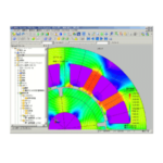
The power mode has a built-in line start analysis feature (Fig.12). The obtained results are shown below (Fig.13-15). It can be confirmed that the rated speed is achieved from the rotation results, and that it starts without any problems. It can also be confirmed that the result is below the maximum current specified in the required specifications. Leakage flux may result from localized magnetic saturation and decrease the torque. Also check to see that localized magnetic saturation and large leakage flux have not resulted from magnetic flux density distribution.
 Fig. 12 Settings of line start analysis
 Fig. 13 Revolution speed results (line start analysis)
 Fig. 14 Current results (line start analysis)
 Fig. 15 Magnetic flux results (line start analysis)
Start Design with JMAG-Express Public
Through reading this report, I hope you were able to see that designing induction motors is efficient in JMAG-Express, and I also hope you were able to see that quick mode alone allows you to consider induction motor design. Like JMAG-Express quick mode, JMAG-Express Public is a trial design tool that calculates basic properties in a second.
JMAG-Express Public is easy to obtain, so please grab a copy of the software and license with the method below.
- How to Download
Access the JMAG-Express Public website and download JMAG-Express Public. - Obtaining a license key
Register a license key from the JMAG-Express Public homepage. - Install and set the license key
Install JMAG-Express Public and input the license key.
Lastly
Lastly, give JMAG-Express a try for your induction motor designs. JMAG-Express Public is a free design tool that can be used by anybody.
(Tetsuya Hattori)
[JMAG Newsletter June, 2014]