Soft Magnetic Composite Application Examples – Single Sided Axial Flux Machines –
Power by Höganäs AB
Contents
Abstract
1. Introduction
1.1. Process overview
1.2. Material overview
2. Single-sided axial flux machine overview
3. Design Outline
3.1. Geometry Definition
4. Model Simulation Setup and Results
4.1. JMAG Model Settings
4.2. Simulation Results
5. Conclusion
Abstract
The past decade has seen significant development in the field of soft magnetic composite (SMC) materials and their application in electrical machines. A large part of this can be attributed to their isotropic magnetic properties, allowing for relatively complex structures to support magnetic flux whilst supressing losses. Furthermore, the material isotropy benefits the thermal performance, allowing heat to dissipate in all directions.
In order to take full advantage of SMC technology in electric motor applications, it is necessary to address the design, material and processing aspects. Radial flux motors are well suited to the axial symmetry that is fulfilled by laminated stacks of electrical steel sheets. Axial flux motors, however, are tricky to manufacture with this approach and provide a good design example for the SMC technology. The stator and rotor manufacturing benefits from the well-established powder metallurgical (PM) compaction process, a single operation that provides a final high density, net-shaped product. Subsequent heat-treatment relaxes the domains of the material and provides mechanical strength and a low loss characteristic.
This document presents a short overview of the SMC technology, from process to powder properties, together with a concept application study. The motor concept is an open-slot, single-sided axial flux machine (SSAFM) with 12 slots and 10 poles, designed to achieve a nominal specification. This concept has been modelled and simulated using JMAG, applying materials manufactured by Höganäs AB that are readily available in the JMAG material database. Details of the electromagnetic design process, model set-up and results are presented.
- For more information on Somaloy®, the Soft Magnetic Composite (SMC) materials from Höganäs AB, please visit www.hoganas.com .
- Alvier Mechatronics
You can see the article in HOW TO IMPROVE AXIAL FLUX MOTOR DESIGN USING JMAG?
In addition, you can download sample data of JMAG of the example concerned when you enroll in EXCLUSIVE INFORMATION of the lower page.
* This site is applied by Alvier Mechatronics. - For more information regarding SMC applications, please visit www.alviermechatronics.com .
1. Introduction
Soft Magnetic Composite (SMC) components are produced by the well-established powder metallurgy process, where compaction of powdered iron can yield high density, net shaped components. Through a reduction in manufacturing yield losses and post-production operations, it is an efficient and cost-effective process. Furthermore, lower energy consumption by comparison to other production technologies can be realised. The SMC materials are suitable for large-scale mass production of components with accurate tolerances, smooth surfaces, no secondary operations and minimal material waste.
The primary characteristic of the SMC materials is its ability to allow the magnetic flux to flow in three dimensions: the individually inorganically coated iron particles create a magnetically and thermally isotropic path which can provide benefits through the inherent freedoms of design. Moreover, the iron particles can be sized for specific applications, allowing the suppression of iron losses as frequency increases: as the particle size reduces, the surface area for the coating provides a greater bulk resistivity, in the region of tens of thousands of micro-Ohm metres, significantly reducing eddy current losses.
Relating the forming of an SMC component to a stack of punched lamination steel sheets underlines the advantages for the SMC process. SMC is formed to a net-shape in a single operation, achievable at speeds of up to 20 components per minute, depending on the size, required density and geometric complexity of the component. The SMC component is a single part, where almost all the powder from the filling shoe forms the component. This can be compared to punched lamination sheets, where a large amount of scrap material is generated, and the individual laminate sheets must be carefully handled, stacked and bonded to form a final assembly in a secondary process. Furthermore, the SMC component can be designed with chamfer or rounded edges in a plane perpendicular to the magnetic flux vector. This may improve the form factor for the coil winding and reduce its weight, saving on high-cost parts.
The intrinsic material properties lead to differences in magnetic, thermal and mechanical properties. Therefore, simply replacing the existing laminated iron core in an electrical machine with an SMC material will typically result in a loss of performance with very small compensating benefits. A lower relative permeability results from coating individual grains, and the use of high purity iron yields higher hysteresis losses: the dominant loss mechanism at low frequencies, particularly when compared to laminated steel. To overcome this, and to take full advantage of the SMC material, it is recommended to design the electromagnetic components with consideration paid to the unique property profile, moving to a higher pole number to increase frequency, for example.
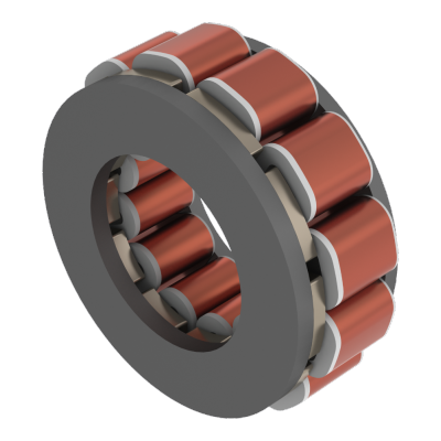
The concept presented here is a single-sided axial flux machine (SSAFM). It is a surface mounted permanent magnet motor with a modular construction concept. The fabrication of the SMC parts greatly benefits from this modular approach, where compaction of a relatively simple stator component and rotor coreback - in single respective press operations - allows coils, with associated insulation, wound off-part, and magnets to be applied prior to assembly. High strength NdFeB magnets are used to provide a strong magnet MMF whilst the pole number is chosen to deliver a compact solution, driving the frequency of operation higher and into a region of comparatively lower loss. The slot-pole combination is selected to provide low ripple characteristics for an open slot stator.
1.1. Process overview
The powder process involves the creation of a base powder mix, which includes all the necessary elements for producing a robust SMC component, compaction and, finally, heat-treatment.
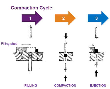 Figure 1. The PM Powder Metallurgy forming process in three steps
The compaction process is depicted in Figure 1, where powder is fed into a die tool cavity before being compacted under high pressure to form the final net-shape component. This is then ejected from the tool and transferred to the heat-treatment. Heat-treatment is conducted under a strictly controlled temperature profile to evaporate compaction lubricants, relax grains boundaries and harden the structure. The furnace can have a specific environment, where gases present in the atmosphere improve the component performance.
The component density is related to the actual pressure of compaction. The higher the component density the more magnetically active material is present. The performance of the material, in terms of loss, at a given frequency is determined by the size of the particles in the initial mix; for lower frequency applications, large particle sizes are best suited. Conversely, high frequency applications will benefit from smaller particle sizes, with an overall larger surface area available for coating. The properties and performance of the SMC material depends upon the powder mixes, discussed below.
1.2 Material overview
Höganäs AB Somaloy® is a family of SMC materials, which are made of high purity iron powders with nanometre-size inorganic surface insulation, as shown in Figure 2. The iron powders are available in several grades with particle sizes of between 50 – 250 micrometres. The Somaloy® family is grouped into performance levels based on the coating properties: 1P, 3P and 5P. The resultant performance of the powders is highly dependent on this coating and its sensitivity to the compaction and heat-treatment processes. The additives - such as lubricants for powder filling and ejection from the die tool post compaction, for example - and the heat-treatment process, must be optimal to yield the desired performance from the component.
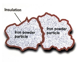 Figure 2. SMC powder particle with electrically resistive coating.
During the compaction phase, there is a physical limit on the pressure that should be applied to the powder in the die tool, which is determined by the pressing force and the part geometry. Under compaction forces that exceed the material limits, the coating will breakdown and the resultant component will not have the electromagnetic properties expected. Where heat-treatment is concerned, the maximum permissible temperature is important for fully stress relieving the grain boundaries after compaction has taken place. This will reduce hysteresis loss and improve permeability, through the removal of impurities, such as lubricants, for example. Exceeding this temperature will breakdown the coating and reduce the electromagnetic performance, along with introducing mechanical defects into the component.
The 1P material provides a base level of performance with a cost-efficient approach. A simple coating is applied, and the heat-treatment of the part is conducted in an air-atmosphere with a maximum temperature of approximately 500 ⁰C.
The 3P grade uses a different additive to 1P to allow for a special steam-atmosphere during the heat-treatment. This brings maximal mechanical strength to the component by a forced oxidation deep into the material structure. The maximum temperature for the heat-treatment 3P is approximately 500 ⁰C.
The most advanced SMC material grade is the 5P, which exhibits the lowest specific loss in the family. A special particle coating is designed to withstand heat-treatment temperatures up to 650 ⁰C, resulting in a component with minimal residual stress post heat-treatment, and the lowest hysteresis losses available for current SMC products.
2. Single-sided axial flux machine overview
Both radial and axial flux machines share a similar electromagnetic arrangement, where magnet flux travels in the denoted direction: the two motor configurations are shown in Figure 3. It is clear that the flux path for a radial motor travels in a two-dimensional plane that can easily be repeated in the axial direction to form a laminated stack. For axial motors to utilise laminations, a complex index punching technique to create a spiral wound stack or the implementation of careful machining on a formed laminated ring would be required, creating a significant challenge for mass manufacture. SMC, therefore, becomes an ideal fit for motor topologies such as the axial flux machine, where the material’s isotropic magnetic properties allow magnetic flux to flow in three dimensions whilst losses are suppressed in relation to the powder grain sizing.
 Figure 3: Flux path in traditional Radial Flux Machine (RFM) and Axial Flux Machine (AFM)
You need to sign in as a Regular JMAG Software User (paid user) or JMAG WEB MEMBER (free membership).
By registering as a JMAG WEB MEMBER, you can browse technical materials and other member-only contents for free.
If you are not registered, click the “Create an Account” button.
Create an Account Sign in
Related Documents
- Soft Magnetic Composite Application Examples – Double-Sided Axial Flux Machines –
- Somaloy®Soft Magnetic Composite (SMC) material for electromagnetic applications, by Höganäs AB (PDF:641KB)
- Alvier Mechatronics
You can see the article in HOW TO IMPROVE AXIAL FLUX MOTOR DESIGN USING JMAG?
In addition, you can download sample data of JMAG of the example concerned when you enroll in EXCLUSIVE INFORMATION of the lower page.
* This site is applied by Alvier Mechatronics.