Contents
1. Introduction
2. Conventional Issues and Proposed Methods
2.1 Issues Regarding SR motor Iron Loss Evaluation
2.2 Proposed Eddy Current Loss Analysis Methods
2.3 Proposed Hysteresis Loss Analysis Method
3. Basic Characteristic Analysis of the Test Machine
3.1 Test Machine Specifications
3.2 Comparing Inductance between the Physical Measurements and the Analysis
3.3 Comparing Torque Between the Physical Measurements and the Analysis
4. Test Machine Verification for Iron Loss
4.1 Calculation Result Comparison for Iron Loss Using a Conventional Method and Proposed Method
4.2 Analyzing Hysteresis Loss and Eddy Current Loss
5. Conclusion
6. References
Overview
1. Introduction
Switched reluctance motors (hereafter referred to as an “SR motor”) are highly durable, robust, and have low costs since they do not use permanent magnets. Since the magnetic flux density waveform of an SR motor’s iron core differs from those of AC motors, such as PM synchronous motors and induction motors, it has been pointed out that accuracy cannot be achieved using conventional iron loss evaluation methods. We used a new method which can evaluate iron loss in high accuracy even with magnetic density wave form for SR motors, and gained positive results when comparing with actual measurements. This paper reports on the findings of this research.
2. Conventional Issues and Proposed Methods
2.1 Issues Regarding SR motor Iron Loss Evaluation
Traditionally, the Steinmetz’s empirical law or expanded methods based on this law have been widely used (hereafter referred to as “conventional methods”). With these methods, each coefficient of the empirical law is determined using the iron loss characteristics which are measured with sinusoidal magnetic flux applied to an electromagnetic steel sheet using the Epstein’s method or single sheet test method. However, the magnetic flux density history of the iron core in the SR motor varies widely from the sine-wave-shaped magnetic flux. For example, magnetic flux density history for the stator ends is as shown in fig. 1. As this figures shows, magnetic flux density is not composed of a sine wave, but higher harmonic components.

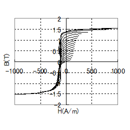
50H1300 loop (lower side)

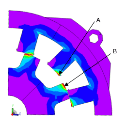
Hysteresis loss distribution
You need to sign in as a Regular JMAG Software User (paid user) or JMAG WEB MEMBER (free membership).
By registering as a JMAG WEB MEMBER, you can browse technical materials and other member-only contents for free.
If you are not registered, click the “Create an Account” button.
Create an Account Sign in


