Contents
1. Introduction
2. Comparing Synchronous Impedances of a 2D Model and a 3D Model
3. Conclusion
1.Introduction
For synchronous motors, 2D simulations have been widely used because of the large computational costs, although impedance varies during operation due to its non-linear properties.
However, a synchronous motor has strong three-dimensional properties; the duct space of an iron core, winding end geometry, and other properties affect magnetic circuits, so the differences between 2D and 3D models need to be identified in advance, and their uses must be differentiated depending on the objective.
This case study makes the differences clear between 2D and 3D models by comparing the synchronous impedances obtained from the analysis results of 2D and 3D models, and shows that all simulation results are very dependent on the nonlinearity of materials.
Key Technologies
- Parallel Computing
A 3D model of a synchronous motor must account for duct space, coil ends, damping winding, and other properties, which can make the model millions of elements large. JMAG’s parallel computing functions makes high-speed simulations achievable for large models. - Time Period Explicit Error Correction (TPEEC) Method
Resistance is extremely small compared to inductance in a short circuit characteristics evaluation, so a simulation must be performed dozens of times until a steady state is reached. The TPEEC method is able to reduce the number of time steps drastically by forcefully shifting from a transient state to a steady state. - Parametric Analysis
Each field current must be simulated for the calculation of synchronous impedance, but by using a parametric analysis, all the simulations can be performed together. - Response Graph
For the simulation results for each field current obtained using a parametric simulation, the case parameters can be set to the horizontal axis and the results of all the cases can be displayed on the same graph by using the response graph function.
2. Comparing Synchronous Impedances of a 2D Model and a 3D Model
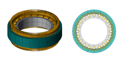
The 2D model and 3D model used in the simulation are shown in figure 1, and the simulation specifications shown in table 1. For the 2D model, the lamination factor was specified accounting for the duct space section by using the homogenization method in the magnetic properties of the stator core (35JN360). This elucidates the influence 3D geometry has on the results. The difference between 2D models and 3D models is whether the magnetic flux in the axis direction exists or not.

3D model (left) and 2D model (right)
Table 1 Simulation specifications for a synchronous motor
| Number of poles | 20 |
| Number of slots | 120 |
| Rated output | 1.8MW |
| Rated voltage | 2200Vrms |
| Rated speed | 300rpm |
| Field current | 120A |
| No. of turns per slot / No. of field winding turns | 3 turns / 50 turns |
Protected content here, for members only.
You need to sign in as a Regular JMAG Software User (paid user) or JMAG WEB MEMBER (free membership).
By registering as a JMAG WEB MEMBER, you can browse technical materials and other member-only contents for free.
If you are not registered, click the “Create an Account” button.


