Contents
1. Introduction
2. Common-mode Voltage/Bearing Current
2.1. Common-mode Voltage
2.2 Bearing Current
3. Direct Coupled FEA and Equivalent Circuit Analysis Approach
4. Use Case
5. Summary
6. References
1. Introduction
Modern inverters for motor drives are utilizing SiC and other wide-bandgap semiconductors to realize faster switching speeds as electric vehicles become more commonplace and requirements for energy-efficient devices become stricter. Faster switching speeds do contribute to higher efficiency but also increase common mode-voltage and the risk of bearing current due to the dielectric breakdown in the bearings. The bearing current can also cause electrical corrosion in the bearings, which can significantly reduce motor reliability. Evaluations that can precisely predict the common-mode voltage, bearing current, and other high-frequency phenomenon at the design stage is vital to devise EMI countermeasures and ensure reliability.
This case study simulates high-frequency pathways accounting for parasitic components of each part via an equivalent circuit and evaluates the high-frequency phenomenon of a permanent magnet synchronous motor using a direct coupled finite element analysis (FEA). We provide some guidelines for modeling equivalent circuits and touch on the accuracy obtained through these approaches.
2. Common-mode Voltage/Bearing Current
This section describes the mechanisms that cause the common-mode voltage produced in inverter-driven motors and the bearing current phenomenon resulting from the common-mode voltage.
2.1. Common-mode Voltage
Common-mode voltage refers to the average voltage across the output terminals (U, V, and W phases) in reference to the ground. Common-mode voltage not only can cause failures and noise in motor-driven systems but also is a fundamental cause of high-frequency phenomenon. Inverter circuits use a PWM control for switching DC link voltage to produce alternating current that drives the motor. The sum of instantaneous three-phase voltage at any point is always 0 in ideal three-phase alternating currents. However, the switching in PWM inverters produce differences in potential between the neutral point potential and ground because all of the phases produce zero voltage vectors at positive and negative connections of the DC link due to dead time and other phenomenon. This is the common-mode voltage. An increase in the common-mode voltage and a higher frequency spectrum are notable inverter characteristics. The broader use of SiC and other wide-bandgap semiconductors can achieve faster switching but can also cause significantly higher common-mode voltage than conventional Si inverters. The common-mode voltage produces common-mode current through the stray capacitance in the motor winding, frame, cable shielding and ground.
2.2 Bearing Current
Bearing current refers to current that uses the motor bearings as current pathways. The current flowing in the bearings produces a small amount of electric corrosion on the raceway and rolling element surfaces of the bearings. The bearing current more rapidly deteriorates and can eventually cause the bearings to fail. Common-mode voltage is considered a primary source of bearing currents. Bearing current breaks down into two main categories: electrostatically induced bearing current and electromagnetically induced bearing current. Electrostatically induced bearing current is a current induced in the rotor through the stray capacitance in the rotor caused by fluctuations in the common-mode voltage. The rotor and frame have an electric potential difference because the rotor is secured to the frame through the bearings. An electric potential that exceeds the dielectric strength of the bearings breaks down the lubricating oil film and arc discharge produces a current in the bearings. Electromagnetically induced bearing current (circulating current) is a phenomena produced due to magnetic imbalance in the motor, which differs from the electrostatically induced bearing current caused by the common-mode voltage. This case study focuses on electrostatically induced bearing currents.
3. Direct Coupled FEA and Equivalent Circuit Analysis Approach
This section describes a direct coupled analysis approach that combines FEA with a lumped-element equivalent circuit to precisely predict the common-mode voltage and bearing currents as high-frequency phenomenon. This analysis approach can simultaneously evaluate both the electromagnetic phenomenon of motors as well as the bearing pathways and other high-frequency phenomenon at a reasonable computational cost. As described earlier, analyses must take into account the stray capacitance between the winding and rotor/winding and frame as well as the parasitic inductance components to accurately obtain the high-frequency phenomenon caused by faster switching in inverter-driven motors. This case study directly couples an equivalent circuit that simulates the main high-frequency current pathways to an electromagnetic FEA that obtains the high-frequency characteristics. Accurate modeling of the stray capacitance of each part that act as the main high-frequency pathways using an equivalent circuit can very accurately simulate the quasi-static electromagnetic phenomenon of the motor and high-frequency phenomenon. This approach can precisely capture spatial distributions of the electromagnetic fields using FEA, while simultaneously evaluating the common-mode voltage produced by high-speed inverter switching and the bearing current induced by the common-mode current.
4. Use Case
This section presents a case study that uses the direct coupled FEA and equivalent circuit analysis approach described in Section 3 to evaluate a permanent magnet synchronous motor. Fig. 4.1 illustrates the model geometry of the motor. Table 4.1 outlines the motor specifications. This case study only focuses on the parasitic components in the motor. Therefore, the modeling does not account for the parasitic components in the external cables and inverter output stage. Fig. 4.2 provides a schematic diagram of the circuit model used for this case study. This model is referred to as Circuit Model 1.
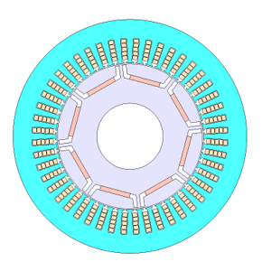
Fig. 4.1 Motor Model Geometry
Table 4.1 Motor Model Specifications
| Item | Value |
|---|---|
| Poles / Slots | 8 / 48 |
| Lamination steel | 35(A) 300 |
| Magnet | NdFeB, Br=1.2 (T) |
| Rated output power | 80 (kW) |
| DC voltage | 600 (V) |
| Max. phase current | 250 (A) |
| Carrier frequency | 20 (kHz) |
| Operating point | 5,000 (rpm), 100 (Nm) (108 A/61 deg) |
You need to sign in as a Regular JMAG Software User (paid user) or JMAG WEB MEMBER (free membership).
By registering as a JMAG WEB MEMBER, you can browse technical materials and other member-only contents for free.
If you are not registered, click the “Create an Account” button.
Create an Account Sign in


