Contents
1. Introduction
2. Verification Method
3. Results
4 Conclusion
5. References
1. Introduction
Mesh is essential for the accuracy and convergence of iterative calculations such as ICCG in the finite element method. If the necessary resolution for required areas is not appropriate, convergence will deteriorate and accuracy will be insufficient. Convergence has been known to generally deteriorate as the aspect ratio of elements increase.
In this report, we will present verification test results for element shapes in the air region near coils and their effect on convergence and calculation accuracy of the ICCG.
This verification test is for AC loss calculations of coils. Square wires in rotating machines are now being used widely and calculations of eddy currents in wires are on the rise. This type of analysis often needs high resolution air mesh around the coil end in order to accurately capture flux leakage causing eddy currents. Here, we will investigate the extent to which mesh resolutions affect accuracy and convergence.
2. Verification Method
The verification test model was composed of 2 wires: one which was forcibly energized with alternating current generating a magnetic field, and the other one produced eddy currents due to that magnetic field (Fig. 1(a)). Eddy current analyses were conducted for 3 mesh models which have the same mesh inside their wires (Fig. 1(b)) and a different mesh in their air regions (Fig. 2).The element size of the air region of model A was set to the large value of 1000 mm; model B was set to 100 mm; and model C was set to 5 mm in the vicinity of the wires. In models A and B, it was confirmed that a spiderweb shaped mesh with high aspect ratio elements was generated around the wire. When element sizes for air are much larger than those for wires, mesh such as spiderweb shaped meshes are more likely to appear..
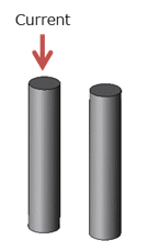
(a) Wire shape
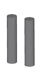
(b) Wire mesh
Fig. 1 Verification test model
Forced AC current of 1A and 1 kHz flows in one of the two wires.
Eddy current loss is calculated in the other wire without energization. The wire diameter is 20 mm, and the wire length is 40 mm.
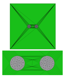
Model A
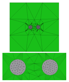
Model B
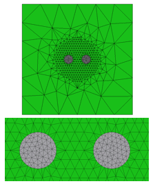
Model C
Fig 2. Wire model and air region meshes
For model A, the element size of the air region is set to 1000 mm; B is set to 100 mm; and C is set to 5 mm in the vicinity of the wires. In models A and B, there is a spiderweb shaped mesh in which many of the air elements adjacent to the wires share a node and have high aspect ratios. In model C, the spiderweb mesh does not exist..
You need to sign in as a Regular JMAG Software User (paid user) or JMAG WEB MEMBER (free membership).
By registering as a JMAG WEB MEMBER, you can browse technical materials and other member-only contents for free.
If you are not registered, click the “Create an Account” button.
Create an Account Sign in


