Contents
1. Background
2. Proposed Method
3. Analysis target
4. Efficiency map computataion and selection of operating points
5. Coupled analysis
6. Loss and efficiency analysis
7. Computation time
8. Conclusion
1. Background
Along with high efficiency of electromagnetic equipment, highly accurate loss analysis is an important subject in electromagnetic field analysis. Permanent magnet synchronous motors and induction motors are often driven by inverters such as PWM system for variable speed operation. It is known that the inverter generates time harmonic components (hereinafter referred to as carrier harmonics) derived from carriers in the current of the motor and increases iron loss. It is important to consider this carrier harmonic in order to accurately calculate the efficiency of rotating machines performing the variable speed operation.
There are two approaches to draw the efficiency map. First is using the plant model generated from FEA models. In order to draw the efficiency map, it requires determining the current vector to achieve highest efficiency at the operating point. This searching requires parametric analysis changing the current vector. By using the plant model, the calculation time can be reduced significantly.
Second approach is using FEA directly to draw the efficiency map. This approach takes longer time than the first approach but it can capture the effect that the plant model doesn’t have such as the eddy current or the effect of time harmonics components.
In this paper, we propose a method that combines two approaches to calculate the efficiency at various operating points considering the influence of time harmonics and other effects in the shorter time.
2. Proposed Method
Fig. 1 shows the flow from material measurement to performing an analysis. The process consists of computing a simple efficiency map, determining operating points, and performing coupled analysis.
Fig. 1 The flow of efficiency calculations taking into account the influence of carrier harmonics
and AC copper loss
It is assumed that the current vector providing the highest efficiency does not change due to the presence or absence of carrier harmonics and AC copper loss.
First, in order to determine the operating points for calculating the efficiency, an efficiency map is computed using a plant model. In this case study, the efficiency is determined without taking into account carrier harmonics and AC copper loss in the inverter.
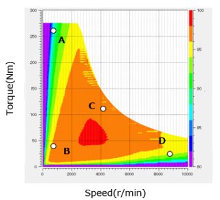
Efficiency map and selected operating points
Layout of the coupled analysis
The current vector controller receives current from the motor and inputs voltage command values to the inverter
You need to sign in as a Regular JMAG Software User (paid user) or JMAG WEB MEMBER (free membership).
By registering as a JMAG WEB MEMBER, you can browse technical materials and other member-only contents for free.
If you are not registered, click the “Create an Account” button.
Create an Account Sign in


