Contents
1. Introduction
2. Issues surrounding the skin mesh generation
3. Improvement for a case where skin thickness is equal to or greater than element size
4. Improvement by enabling extrusion in two directions
5. Summary
6. References
1. Introduction
Electromagnetic field analysis using finite element method that takes into account the eddy currents has been widely used in designing electrical equipment lately. For example, when evaluating calorific value in induction heating, it is essential to account for eddy currents, and when evaluating loss/efficiency of motors and transformers as well as the response of the solenoid valves, the effect of eddy currents cannot be ignored. The mesh plays a very important role in analysis when accounting for these eddy currents.
The eddy current flows mainly in the vicinity of the conductor surface, and its magnitude decreases exponentially from the surface. Therefore, in order to accurately simulate eddy currents in the analysis, it is extremely effective to make a layered skin mesh near the surface by estimating the skin thickness. Therefore, it is highly desirable to generate skin mesh steadily at the skin thickness designated by the analyst, when running the eddy current analysis. For this purpose, we have improved the reliability of skin mesh generation for JMAG-Designer in this work, and thus, its details are introduced in this paper.
2. Issues surrounding the skin mesh generation
Three-dimensional skin mesh generation by JMAG-Designer Semi-Auto Mesh is implemented by creating layered elements in such a manner that nodes on the boundary surface of the model to be skin meshed are extruded towards the inside, after generating tetrahedral mesh. However, this method poses the following challenges and often fails to generate skin mesh as specified, depending on the setting and geometry.
A) Skin mesh generation tends to be inadequate when skin depth is about the same as or greater than the element size
- When nodes on the red boundary surface are extruded for an amount that is greater than the element size as shown in Fig. 1(A), skin mesh is not generated as specified since elements are largely distorted or turned inside out, which is caused by the positional relation with interior nodes located right inside the boundary surface.
- This applies to the case where skin thickness is likely to be set large since heat is generated by eddy currents deep inside the skin due to heat induction.
B) There are instances when an extrusion in more than two directions may be required at locations such as the boundary surface where parts are in contact.
- When extruding nodes on the red boundary surface, such as shown in Fig. 1(B), skin mesh cannot be generated since layered elements become largely distorted when extruding nodes (on the contact boundary surface between parts) only along that contact surface.
- This applies to the cases when generating skin mesh for multiple parts that are not insulated, or a model which is originally composed of only one part, but is intentionally divided for an analysis purpose..
C) Skin mesh generation is likely to be inadequate in areas that are not smooth, such as corners.
- When nodes on both the red boundary surfaces enclosing the corner, such as shown in Fig. 1(C), skin mesh cannot be generated as specified since elements become largely distorted or turned inside out, depending on the skin thickness and the extrusion direction.
D) Skin mesh generation tends to be inadequate in locations where local geometry(edge length, width of the surface, thickness of the solid)is not sufficiently large compared to the skin thickness.
- When nodes on both edges of the elongated light blue surface, such as shown in Fig. 1(D), are extruded, it is difficult to generate a skin mesh as specified, since elements tend to become largely distorted or turned inside out.
- Small geometries, such as those mentioned above, may be generated inadvertently during the processing of the CAD data, other than those existing on the actual drawing.
Among all these problems, improvements were made for two of them, A) and B), and are explained in chapters 3 and 4, respectively.
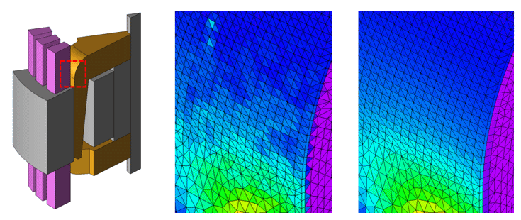
Joule loss density distribution of rotor core due to eddy currents in a claw-pole type alternator
Left: Overall model, Middle: Results before improvement (enlarged view), Right: Results after improvement (enlarged view)
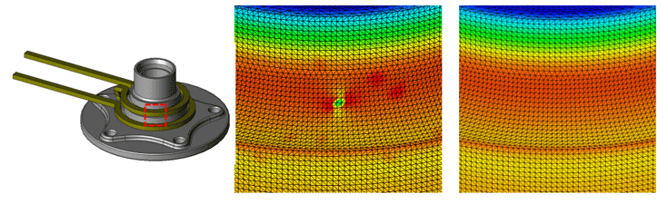
Joule loss density distribution of work piece due to eddy current in induction heating model
Left: Overview of the model, Center: Results before the improvement was made (Enlarged view), Right: Results after the improvement was made (Enlarged view)
You need to sign in as a Regular JMAG Software User (paid user) or JMAG WEB MEMBER (free membership).
By registering as a JMAG WEB MEMBER, you can browse technical materials and other member-only contents for free.
If you are not registered, click the “Create an Account” button.
Create an Account Sign in


