Overview
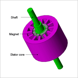
It is difficult to accurately evaluate a motor’s characteristics in advance using the magnetic circuit method or other methods, therefore it is necessary to run an electromagnetic field analysis using the finite element method (FEM).
In this example, how to obtain the efficiency with a sinusoidal wave voltage drive at a rotation speed of 1,800 r/min and voltage amplitude of 40 V.
Voltage Waveform/Current Waveform
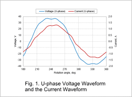
The Fig. 1 shows that there is displacement between the phase voltage and phase current. This phenomenon occurs due to inductance. In addition, the apparent power is 78.9 VA when calculated from each effective value and converted to the three phases.
Active Power Waveform/Power Vector Plot
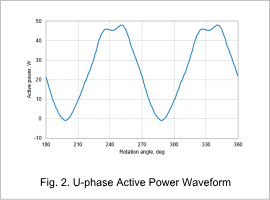
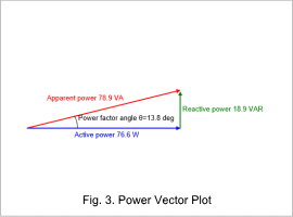
The U-phase active power waveform is shown in Fig. 2, and the power vector plot is shown in Fig. 3.
When the U-phase average active power is calculated according to Fig. 2 and converted to the three phases, the value is 76.6 W. The power factor and power factor angle are calculated from the ratio of the active power and apparent power, which is 0.97 and 13.8 deg for this motor. The reactive power can be obtained from the apparent power and power factor angle and displayed in a vector plot as in Fig. 3.
Output Characteristics
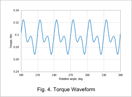
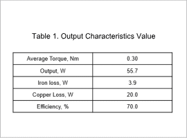
The torque waveform is shown in Fig. 4 and the output characteristics value is shown in Table 1.
The average torque 0.30 Nm can be obtained from Fig. 4. The motor output 55.7 W can be calculated from the obtained torque and rotation speed. Note that the copper loss consumed by the coil is 20.0 W. The efficiency of this motor, 70.0 % is calculated from the output, iron loss and copper loss.
